


Hydraulic Implement Lift Demanding Less Pumping
Page 42
If you've noticed an error in this article please click here to report it so we can fix it.
A Resume of Patent Specifications that Have Recently Been Published
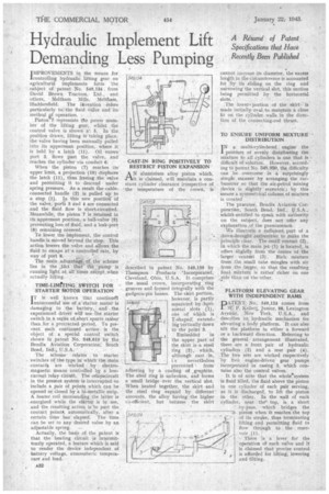
IMPROVEMENTS irt the means for 'controlling hydraulic, lifting gear on agricultural implements form the subject of patent No. 549,134 . from David Brown Tractors,Ltd., and others,. Meltham Meltha,in, Huddersfield. The invention refers particularly to the fluid valve and its method if operation„
Piston 7 represents the power member of the lifting gear, whilst the control valve is shown. a': 5.. In the position drawn, lifting ir taking place, the valve having been manually pulled into its uppermost position, where it is held by a latch (11). Oil enters ' port 3, flows past the valve,, and reaches the cylinder via conduit 6: When the piston (7) reaches its upper limit, a projection (In) displaces the latch (11), thus freeing the vslye and permitting it to descend under spring pressure. As a result the-cableconnected handle (2) is pulled up to a stop (I). In this new position Of the valve, port 3 and 4 are connected and the fluid flow is short-circuited. .Meanwhile, the piston 7 is retained in its uppermost position, a ball-valve (9) preventing loss of fluid, and a leak-port (8) remaining covered.
To lower the implement, the. control handle is moved beyond the stop. This action lowers the valve and allows the fluid to escape at a controlled rate, by way of port 8. '
The main a,dvant4cf, the scheme lies in -the fa"ct that flie 41inanis running light at alrtipaea.exCept..when actually lifting.
TIME-LIMMNG SWITCH FOR STARTER MOTOR OPERATION iT is well known that continuet unsuccessful Use of a, starter motor is damaging to the battery, : and' the experienced driVer. wilt Use: the starter switch in a series of.:short spurts rather than for a protracted period, To pre-' vent such continued action is the object of a' special 'control switch shown in patent No. 548,610 by the, Bendix AviatiOn Corporation;. South
Bend, U.S.A.
The scheme relates to starter switches of the type in whichthe main contact are worked by electromagnetic means controlled by a lowcurrent relay ciretit.. The relayecircuit in the present system. is. interrupted .to include a pair of points. which can be opened or closed by a bi-metallic strip. A heater coil surrounding the tatter is -energized while the starter is in use, and the resulting action is "to part the contact point, automatically, after a certain time has elapsed. The time can be set to any desired value by an
adjustable spring.
Actually, the basis of the patent is that the heating circuit is intermittently operated, a feature which is said to render the device independent of battery voltage, atmospheric tempera ture and load.
AN aluminium alloy piston which, it is claimed, will maintain a constant cylinder clearance irrespective of 'the temperature of the crown, is
described in patent No. 549,159 by Thompson Products 'Incorporated , Cleveland, Ohio, U.S.A. It comprises the usual crown, incorporating ring grooves and formed integrally with the gudgeon-pin bosses. The skirt portion,
544950—'• separated byhQri
however, is partly zontal slots (1), one of Which is
2 T-shaped; extending vertically down to the point 3.
Embedded in the upper part of the. skirt is a steel ring (2), which, although cast in, 3 i a nevertheless prevented from adhering by a coating of _graphite. The steel ring is unbroken, and forms a small bridge over the vertical slot. When heated together, the skirt and the steel ring expand by different amounts, the alloy having the higher co-efficient, but because the skirt cannot increase its diameter, the excess length in the circumference is accounted for by its sliding on the ring and narrowing the vertical slot, this motion being permitted by the horizontal slots. .• . • The lower• portion of the skirt is made initially oval to maintain a close fit on the cylinderwalls in the direction of the connecting-rod thrust.
TO ENSURE UNIFORM MIXTURE DISTRIBUTION INa multi-cylindered engine the problem of evenly disttibuting the mixture to all cylinders is one that is difficult Of solution. However, according to patent No. 648,950, the difficulty can be overcome in a • Surprisingly simple' manner by arranging the' Carburetter so that the air-petrol mixing device is slightly eccentric ; by this means a symmetrical column of mixture is cleated
The patentee, Bendix Aviation Corporatien. South Bend, Ind., U.S.A., whi.M.entitled to speak with authority on the subject, does . not :offer any explanation ,of the pnenomenoii.
We illustrate a sufficient, part of a down-draught earbitretferto make the principle clear. The small venturi (2), in which the main jet(1) is located, is offset lli,ghtly from the Centre -of the larget ventrisi (3). Rich, mixture from the small tube mingles With air from -the :Jagger, so that the resulting final mixture is rather' richer on one side than on the other.
PLATFORM ELEVATING GEAR WITH INDEPENDENT RAMS DATENT No, 549,124 comes from
W: P. Kellett, Junior, 88, Lexington Aveutie, New York, U.S.A., and describes an hydraulic' mechanism for elevating a body platform. 'It can also tilt the platform in either a forward or a backward direction. Referring to the general arrangement illustrated, there are a' front pair of hydraulic cylinders .(2) and a rear pair (4) The two sets are Worked respectively by two engine-driven gear pumps incorporated in casing 3, which contains also the control valves.
It .is of -note that the wbolesystem is fluid filled, the fluid above the piston in one cylinder. of each pair serving, as it is discharged, to lift the piston in the other. In the wall of each cylinder, near the' top, is a short
" by-Pass, which bridges the piston when it reaches the top of its stroke, thus terminating lifting and permitting fluid to flaw through to the reser voir (1).
• There is a lever for the • operation of each valve and it is claimed that precise control is afforded for lifting, lowering and tilting.