


A Gearbox Embodying Hydraulic Control
Page 54
If you've noticed an error in this article please click here to report it so we can fix it.
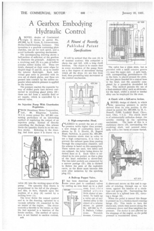
ANOVEL deice of Continental origin is shown in patent No. 457,908, by E. Grote, 5, Carmerstrasse, Berlin-Charlotteiaburg, Germany. This invention is a gearbox containing plate clutches, one set for each speed, and a novel hydraulic operating mechanism.
The accompanying drawing shows a half-section of sufficient of the gearbox to illustrate the principle. Adjacent to a.revolving wall (5) is a pair.of hollow annular _rubber bodies (3). These are firmly damped at their outer edges by shaped rings (1 and 2). so as to render the interior fluid-tight Each individual gear ratio is provided with its own set of clutch plates, and these are pressed into contact by the rubber expander when suitable pressure is applied to the interior.
The pressure reaches the expander by way of drilled ports (not shown) connected to revolving gland joints (4) ; these are fed from a suitable fluid or air supply, which is controlled by a selector valve.
An Injection Pump With Unorthodox Regulation.
FROM Hesselman Motor Corporation, Ltd., 56, Kingsway, London. W.C.2, comes patent No. 457,861 containing particulars of an interesting method of regulating the output of an injection pump. Instead of directly controlling the discharge, this scheme limits the quantity drawn in on the suc
tion stroke. Referring to the draw. ing, fuel from space 5 is drawn via a valve (6) into the working space of the pump. The quantity thus drawn is proportional to the fall of the plunger. and this, in turn, depends upon the position of a stop (4) carried by a rodking lever (1).
The lever forms the output control and is, in the drawing, operated by a vacuum cylinder (2) connected to the air intake of the engine. The driver controls a throttle in the intake, so that the fuel injected is a function of the intake 'suction. The method of operation is hot limited to suction control.
1344 It will be noticed that the cam (3) is of unusual contour; this comprises a sharp rise and fall, with a long dwell between. The object is to ensure that in every revolution of the pump there are a few degrees of movement during which all the stops (4) are free from load, thus permitting easy movement of the control mechanism.
A High-compression Head.
CiAlmED to permit the use of compression ratios higher than normal, a new design of combustion head is shown by H. S. Hewitt, 31, Regent Road, Surbiton, la patent No. 458,368. This inventor states that in order to use a high .compression, it is vital to prevent the exhaust 'gases from passiag through the compression chamber, and the scheme is based on this assumption. Three valves are used, two inlets and one exhaust, the latter being shown by dotted lines at 2. Each valve is enclosed in its own pocket, so that a plan of the head resembles a clover-leaf. The two inlet pockets are connected by a narrow passage (3) ; this is claimed to flatten the peak of the explosion curve, as the flame must traverse this neck after initiation by the sparking plug (1).
A Built-up Poppet Valve.
IT has been American practice for some years, past to construct valves by casting an iron head on to a steel stem, but this method allows little choice of material. To build up a valve out of any desired alloy is the object of a scheme shown in patent No. 457,355 by F. E. Bullock, Cotherstone, Warwick Avenue, Coventry.
The valve has a plain stern, but is provided with a small concave groove (1) near the upper end. A split bush, with corresponding protuberances (3) in the bore, is placed around the stem, the two pieces inserted in a conical bore in the head, and the assembly completed by a pressed-in dovetailed lid (2). This method permits the use of a heat-resistant alloy, such as sikbrorne, for the head, whilst a nickel or similar alloy can be employed for the stem.
A Clutch with a Self.servo Action.
ANOVEL design of clutch, in which he operating pressure is partly derived from its own motion, is . disclosed in patent No. 457,989, by R. C. Russell, 3,549, Lynfield Road, Cleve-land, Ohio, U.S.A. The clutch itself is of substantially orthodox design, the novelty residing in the • operating mechanism. The basis of this is a stationary sleeve (3), surrounding the revolving shaft, and screwed externally with a few turns of coarse thread.
A sleeve-nut moves on this and is capable of rotating, through one or two turns, against the tension of a clocktype coil spring (4). Surrounding the sleeve-nut is a splined boss (5), carrying a flange (2).
When the pedal is moved this flange is pressed on to a friction-faced rotating flange (I). This tends to turn the sleeve-nut, which then screws along the stationary sleeve and thus 'amplifies the pressure. The device is not affected by the stoppage of the engine, as the pedal pressure is transmitted direct.