


THE AUTOMATIC ADJUSTMENT OF BRAKE STOPS.
Page 34
If you've noticed an error in this article please click here to report it so we can fix it.
A Resume of Recently Published Patent Specifications.
OND of the difficulties that thedesigner has had to deal with in the design of brake systems is that, as wear takes place in the facing of the shoe, a greater space is formed between the position where the shoe contacts with its drum and where it comes to rest in the " off " position.
In the case of positive stops attached to the back plates, a greater movement of the expander had to be provided when the brakes were worn than when new. In some cases adjustable stops were provided, but these were difficult to set while the' drum was in place. In some cases the two shoes were made to meet when in the " off " position ; neither of these plans has, however, been found completely satisfactory. The invention described in specification No. 302,005, by the Triumph Cycle Co., Ltd., and
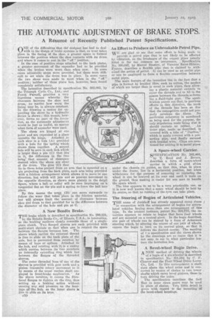
Frank Parnell, provides a. very ingenious means whereby the clearance between the shoe and drum, no matter how worn the lining May be, is always constant. In the drawing a means for expending the shoes by a hydraulic device is shown; this means, however, forms no part of the ins ention, as the automatic adjustment would be just as useful, no matter what form Of expander were Used.
The shoes are hinged at one point and are expanded at a place opposite the hinge. Attached ,to each shoe is a link "(A) provided with a hole for the 'spring which draws them together. A second hole will be seen in each link which is larger than a pin: (C) that lies in it, the difference in the two being' that amount of clearance desired when the shoes are clear of the drum. The pins (C) that
lie in these holes project from an arm that is mounted on a pin projecting from the back plate, each arm being provided with a friction arrangement which allows it to move in one direction, but which will jam and so prevent Movement in the opposite direction, as shown more plainly in the det.1 figure, where a ball or roller will be seen impinging on „a tangential flat on the pin and a spring to force the ball into place.
By this means the arms (B) can move outwards to follow the wear that takes placein the friction material, but will always limit the amount of clearance between shoe and drum to that provided for in the difference between the diameter of the hole and pin at C.
A New Bendix Brake.
THE brake which is described in specification No. 299,121,
by the Bendix Brake Co., of Illinois, U.S.A., is interesting, as the braking surfaces closely resemble those of a singleplate clutch. Two flanged sleeves are each provided with multi-start threads so that when one is rotated the space between the flanges becomes less. The sleeve which carries the external thread is free to slide on the back plate of the axle, but is prevented from rotation by means of keys or plines. Attached to the hub, and rotating with it, is a casing which carries between its two members an internally extending ring which lies between the flanges of the threaded sleeves.
The outer threaded boss of one of the sleeves is provided with gear teeth and a pinion transmits rotary movement to it by means of the usual cardan shaft em
ployed in front-brake application. As the sleeve revolves, it causes the fibrefaced flanges to tighten on the ring, thus setting up a braking action without causing any end pressure on the bearings pf the hub, as the inner sleeve is free to slide on its keys.
c50 An Effort to Produce an Unbreakable Petrol Pipe.
are glad to see that some effort is being wade to provide a petrol pipe that is not likely to be affected by vibration, as the breakages of the copper pipes usually
fitted is far too common an occurrence. Specification No. 800,047, by Marcel I3ussier, of Varenne
France, describes a flexible pipe that is claimed to withstand the action of petrol. It can be used as an entire pipe or can be employed to form a flexible connection between metal pipes.
The main feature of the invention lies in the fact that a pipe is 'formed by braided fibre, such as cotton, the meshes of which are larger than is usual in such pipes, thus allow
ing a• plastic material entirely to cover the threads and to fill in the spaces between the threads, soforming a fluid-tight pipe. The specification points out that, in previous efforts in this direction, the mesh of the threads has been so fine that the compasition could not properly envelope the fibres. No particular substance is mentioned as being used for the purpose, the only Stipulation made being that it should contain no rubber. An inner pipe, made • as described, is covered with a tube of "Duritee," which is again covered with a protecting. pipe, and finally encased with braided wire. Clips are mentioned for uniting it to metal pipes.
A Spare-wheel Carrier.
SPECIFICATION No. 302,464, by T. Reed and J. Brown, describes a form of spare-wheel
carrier in which a grid slides under the chassis on guides, so that this, when, in place under the frame, lies in a horizontal position, but when withdrawn for the purpose of removing or replacing the wheel it can be lowered at its rear end until it rests on the ground, thus making it easier for one man to handle the spare wheel. The idea appears to us :to be a very practicable one, as it is now well known that a spare wheel should be held by Its centre, so that no rubbing of the tyre can take place.
The Steering of Bogies of Articulated Vehicles. THE name of Jonkhoft has already appeared many times in connection with the arrangement of bogies for artictis lated vehicles having-. more = than one arrangement of this type. In the present instance, patent No. 301,777, the invention appears to relate to bogies that have four wheels and are mounted on a central pivot. In the bogie described, one pair of wheels can be steered by a form of Ackerman steering which, by altering the course of one pair of wheels, causes the bogie to turn on its central pivot, so that it
follows the desired course. The wording of t :e specification and the views shown by the drawings are so vague that it is not easy to see in what particular feature the invention lies.
A Bevel-wheel Bogie Drive.
A NEW method of driving the wheels of a bogie of a six-wheeler is described in specification No. 301,584 by C. P. Cleaver and the Four Wheel Drive Lorry Co., Ltd. In this arrangement a shaft runs above the wheel axles and is convected by means of chains to two lower shafts which carry bevel pinions, these in turn driving the axles.
The specification mentions the fact that in some cases gears may be used in plate of chains. Very little detail is given with regard to the' mounting • Of the bevel-wheel housings.