An Automatic Cut-out for Battery and Coil Ignition.
Page 25

If you've noticed an error in this article please click here to report it so we can fix it.
WEN .battery and coil ignition is utilized for the enginesof vehicles there is the possibility of the engine stopping just at the point where the spark is occurring, and, consequently, there is a risk of the battery being drained of current unless the ignition be switched .off.
A device to obviate this possibility has been protected by F.
Freeguard and, F. 0.
Beisiegel, of 6, rierdon Road, East Hill, Wandsworth, London, &WAS. It consists of an automatic cut-out of the kind in which two contacts arranged in the ignition circuit are, while the engine is running, maintained in contact through the medium of a diaphragm which is controlled by the pressure variations in the inlet valve of the engine, the contacts-being sa.arranged that the ignition circuit is broken immediately the craultshaft ceases its rotation.
This is not the first time tt device of this type has been utilized, but previously, the diaphragm' was held between a easing and a domed lid for this casing, one of the contacts being secured to the lid and the other carried by the diaphragm, the chamber between the lid of
the diaphragm communicating direct with the inlet pipe.
. The disadvantage of this method is that combustible gas or vapour may find its way into the chamber and form an explosive mixture which is liable to be ignited by. any sparking occurring between the contacts.
In this new form, this trouble is oh
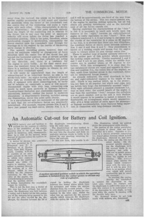
viated by holding the diaphragm between two domed plates which limit its movement and isolate the suction chamber from the contact points. One plate is provided with a nipple for connection to the inlet pipe, whilst the other has an aperture for the screwed spindle which connects the diaphragm with the spring for the moving contact. The illustration which we publish shows the arrangement quite clearly. The portion of the casing containing the contacts is closed (but not hermetically) by a cover. Opposite to -Oda cover is a convex structure comprising two domed plates between which is held the diaphragm. Secured to, and insulated from, the casino.' are the two terminal blocks. On the screwed spindle connect,.
ing the diaphragm with the contact blade is an adjusting nut with a lock nut to permit proper spacing of the contacts when the engine is not running. The outer domed plate carries the nipple which communicates with the inlet pipe, and it will be seen that there is no passage, whatever which will permit -combustible gas to react the contacts.
in starting the engine, directly the crankshaft is rotated the depression in the inlet pipe closes the contact and the diaphragm is sufficiently large to enable this contact to be maintained even if the depression be only slight, as happens when the engine is running with the throttle fully open.
Mr. I3eisiegel wishes to get into touch with makers, etc., interested. Oil


