TECHNICAL ASPECTS
Page 23

Page 24

Page 25

If you've noticed an error in this article please click here to report it so we can fix it.
of
THE MULTI-CYLINDERED ENGINE.
THE first portion of Lids article was
published in our issue for last week. It began by pointing out that there are many characteristics of the
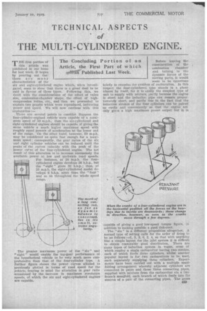
six and eight-eylindered engine which, when investigated, seem to show that there is a great deal to be said in favour of these types. Following this, we dealt with the considerations of the effect of valve .size, combustion-chamber shape, the effect of highcompression ratios, etc., and then we proceeded to explain two graphs which were reproduced, indicating power and speed. We will now continue with this explanation :— There are several points to consider. Suppose the four-cylinder-engined vehicle were ea.pahle of a maximum speed of 50 m.p.h., then the six-cylinclered and eight-cylindered engines should be capable of giving the same vehicle a much higher maximum speed with roughly equal powers of acceleration at the lower end of the range. On the other hand; however, 50 m.p.h. may be considered as quite fast enough for a maximum speed; consequently, the gear ratios of the six and eight cylinder vehicles can be reduced until the peaks of the curves coincide with the peak of the power cteve of the four-cylindered engine. The net result of this alteration is to increase enormously the available power at low and moderate road speeds.
For instance, at 20 m.p.h. the four cylindered engine develops 20 b.h.p., but the "eight" gives 32 b.h.p.; thus, at 20 m.p.h. the eight-cylindered model de velops 6 b.h.p. more than the -"lour " and so on throughout the whole speed range.
The greater maximum power of the "six" arid "eight" would enable the top-gear performance of the hypothetical vehicle to he very much more comprehensive than that of the four-cylinder type. A further figure shows the power curves alluded to previously plotted in terms of road speed for the ;vehicle, bearing in mind the alteration in gear ratio occasioned by the increase in maximum revolution speeds, of which the six and eight-cylindered engines are capable. Before leaving the consideration of the , combustion chamber and turning to the dynamic forces of the moving parts, it would seem to be opportune briefly to examine the problem of carburation. In this respect the four-cylindered type stands in a plane almost by itself, for it is easily the simplest type of unit to supply with mixture, partly because the engine is short and the induction pipe can remain proportionately short, and partly clue to the fact that the induction strokes of the four cylinders can be paired up easily and convenientlyso that the engine not only gives a high maximum power output but it is capable of giving a good low-speed torque figure, in addition to making possible a good tick-over.
The "six!' is a different proposition altogether. A normal type of setting calls for the order of firing to be as follows :-1, 5, 3, 6, 2, 4, so that with anything like a simple layout for the inlet system it is difficult to obtain reasonably good distribution. There are many types of induction system in vogue, some of which ,employ a single carburetter having two strokes. each of which feeds three cylinders, whilst another popular layout is for two carburetters to be used, each separately supplying three cylinders. Experiments have been carried out with a multiple manifolding arrangement whereby adjacent cylinders are connected in pairs and these three connecting pipes, supplied with mixture from the carburetter via a two-. • branch' manifold, each branch of which feeds into the centres of a pair of the connecting pipes. The gases 039 have a very tortuous path, but the saving grace in the system is the fact that thr path to each cylinder is of approximately equal length. Equal power impulses (at least, at low speeds) are therefore attained. Despite all the difficulties, however, a really welldesigned manifold employing a single carburetter and suitably heated can be made to function quite satisfactorily, albeit not quite so efficiently at certain speeds as the four-cylindered counterpart. 4 Cylinders
97mm 136rom
With the eight-cylindered engine distribution is somewhat' easier, but much depends upon the crankshaft arrangement. If the throws of the cranks lie in two planes at right angles to each other, as they should do, it is clear that by coupling two four-throw cranks. together the firing impulses will be even, and at the same time the carburation problem will be almost as easy as on a "four." There is, however, a slight
1 disadvantage to this arrange ment of throws, which will be discussed later, and it has been found in practice that it is preferable to arrange the crankshaft so that the two cranks for the two outer pairs of cylinders lie in one plane and the other cranks for the inner four cylinders at right angles.
With this arrangement the firing strokes are peculiarly irregular, taking each group of four cylinders in line. The carburation of the engine, therefore, is a difficult matter. One manufacturer has got over the trouble by fitting a twin carburetter and two manifolds, one of which supplies the inner four cylinders and the other the two outer pairs. There, are two choke tubes, so that lite two systems work quite separately. On the other hand, however, the straight inanifold, supplied with mixture from one or two carburetters, seems to work fairly satisfactorily in practice, al,/ \ A though with a slight
loss in overall efficiency. loss in overall efficiency.
The dynamic characteristics now claim attention. The primary advantage of either a " six " or an " eight ' is due to' the fact that for a given capacity the cylinders are of smaller
dimensions; cons equently, the weight of individual sets of working parts is reduced, which, in turn, means that the inertia stresses at high speeds are proportionately lessened. This makes the bearing loads much smaller, so that, size for size, they are capable Of standing up satisfactorily to higher rates of revolution speed, or, conversely, the bearings themselves can be made smaller without running any risk of overloading. There is one feature, however, of the multi-cylindered engine W■h c 11 is somewhat incidental to the main issue, but nevertheless
c40 important. As the number of throws is raised O must the overall length of the crankshaft be increased also, which, of course, assists the tendency for the shaft itself to vibrate torsionally. The eight-cylinder crankshaft, therefore, must be relatively stiffer than the "six" and the "six," in turn, relatively stiffer than the 'four" Thus, all the journals have to be increased in diameter to give the shaft the requisite torsional strength, but the journals may be made proportionately narrower (still retaining the same bearing area) if it be necessary from the point of view of compacting the engine. Another feature which never, fails to make an appeal is the smooth torque provided by the " six " and "eight," a characteristic which carries with it the possibility of a lighter flywheel.
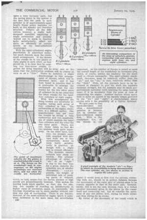
We now .come to that much-discussed and often misunderstood questionof balance. Let us consider the four-cylindered engine first. With a flat crankshaft (i.e., all the throws in one plane) it would seem at first that the pistons, connecting rods, etc., should be in perfect balance, because the movements of the outer pair of pistons seem to be exactly opposite to that of the inner pair. Unfortunately, this is not the case, because there is a rather Peculiar movement given to the piston by the crankshaft and connecting rod. Let us consider the movement of any one piston, first, during its down stroke and then during its up stroke. By virtue of the movement of the crank which is away from the vertical, the piston en its downward motion rapidly accelerates to full speed and reaches its maximum when the throw of the crankshaft and the centre line of the connecting rod 'make a right angle with each other. (This ,characteristic Is shown in an illustration.) Now this point depends entirely upon the length of the connecting rod in relation to the throw, but in any case the point of maximum velocity will occur before the throw has reached a horizontal position. This is the point, therefore, where acceleration changes to deceleration, consequently the forces exerted upon the crankshaft (and through the bearings on to the engine) by the inertia of the moving parts change in direction.
The upward travelling piston, however, does not reach its maximum velocity or change-over of force direction until the centre line of the throw has got beyond the horizontal position; thus at certain periods all the inertia forces of the four cylinders are acting in one direction, and there is a tendency for the engine to move bodily. At the dead centre positions the resultant force is downwards, consequently there is a tendency for the engine to vibrate up anti down at twice crankshaft speed.
It will easily be appreciated that the length of connecting-rod is an important factor, as also is the stroke-bore ratio. An engine having cylinders of small bore with an excessively long stroke for the pistons will, if equipped with short connecting-rods, be badly out of balance, or, conversely, a more or less squaredimensioned engine with very long connecting-rods would be much more perfectly in dynamic balance. Constructional limitation and combustion-chamber considerations, however, confine the layout to moderate dimensions. A diagrammatic drawing, included among the illuStrations, shows this point quite clearly.
In a six-cylinderecl unit the movement of the pistons is such that the out-of-balance forces are practically neutralized. For example, suppose pistons Nos. 3 and 4 have just passed top dead centre, pistons Nos. 1, 2, 5
and (3 will be approximately one-third of the way from the bottom of the stroke. The two centre pistons are, if the engine be moving, pulling upwards, but all the others are pushing downwards, and so the vectorial total of all the forces cancels out.
Having explained the characteristics of the "four " in full it is necessary to touch only briefly upon the features of the "eight," Lecaus.e an eight-cylindered engine is really equivalent to two "fours." With the cylinders numbered 1, 2, 3 and 4 lying in one plane and the cranks of the remainder in a plane at 90 degrees to the first, it is obvious that there are two vibrations, the resultant forces of which occur between cylinders Nos. 2 and 3 and Nos. 6 and 7. This phenomenon is known as a rocking couple and means that the engiee tends to vibrate about its own virtual centre line.
There is another type of layout (already referred to in the earlier part of this article) which overcomes the rocking couple entirely. Cranks numbered 1 and 2 and 7 and 8 are in one plane, whilst the middle four cranks are in another plane, at 90 degrees to the former. With this arrangement it is clear that the two unbalanced forces are equal and opposite in direction and position (Le., the centre line of the engine), so that, apart from internal stress in the crankcase, there are no unbalanced forces present.
As already indicated, the chief drawback to both six and eight-cylindered engines is the length of the unit. There is one method which, up to the present, has not been at all popular, but which may come into use before very long—the horizontally opposed "eight." With eight cylinders athwart a common crankcase (i.e., four on each side), the overall length of the engine is less than the equivalent "four," because the cylinders are so much smaller, and as the unit is very shallow it would appear to be possible to install it beneath the floorboards, an arrangement which would, unquestionably, give a large amount of extra space for passenger or luggage accommodation, these features being important in connection with long-distance coaches.


