


Korn Drivers &Mechanics
Page 20
Page 21
If you've noticed an error in this article please click here to report it so we can fix it.
TEN SHILLINGS WEEKLY is paid for the best communication received, and one penny a line of ten words for anything else published, with an allowance for photographs.
Send us an account of any sPecial incident of your work or exPerience. If suitable, we will edit your notes, supply a sketch Wheh required, and pay you for everything published. Mention your employer's name, in confidence, as evidence of good faith. Address to The Editor, THE COMMERCIAL MOTOR, Rosebery Avenue, London, E.G.
Light Up Your Lamps At
5.28 on Thursday ; 5.30 on Friday ; 5.32 on Saturday; 5.36 on Monday ; 5.37 on Tuesday ; 5.39 on Wednesday.
The Following Method Is An Easy One for Testing Engine Alignment.
The sender of the following communication has been awarded the 10s. prize this week.
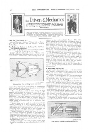
[1425] " (LlandatT) writes :—" It has often been the case in my experience when carrying out an overhaul to a vehicle that, after having taken the engine down for repairs, upon making an examination of the gearbox it is found that there is no necessity to take this unit out of the frame.
" The contribution which I send bears on this matter, and no doubt its inclusion in your 'D. and M.' pages, together with the sketch I enclose [We have had this redrawn—En.] will be of interest to my fellow mechanics. The tools which are made to effect the lining up consist of two forms of scribers, made to engage the rim and face respectively of the flywheel ; these should be constructed out of mild-steel bar,
in. diameter.
"Before they can be made to suit any particular chassis, however., it is first necessary to drop the engine into position, and bring it to correspond with the holding-down bolt-holes, then, with a couple of -templates made with wire, one is able to obtain the length of rod required for making the scribers.
"This is effected by leading one piece of wire from the universal-joint flange, forward of the gearbox, to the nearest face of the flywheel rim, and another piece is led from the same flange to the circumference of the flywheel. These templates, of course, would be bent to the shape shown in the sketch, which depicts the finished scribing tools. " After cutting the rods off to suitable lengths, they should be forged flat. at one end. and drilled ready for D4
bolting to the universal-joint flange. The large scriber, being made to allow for adjustment, must be flattened at both ends, and one or two holes of suitable diameter drilled in that extremity which will come nearest the flywheel, the object being to enable the pointed portion of the tool, when bent at right angles and screwed as shown, to be adjusted to the wheel rim. After providing the shorter scriber with a. point, the necessary tools are finished.
The sketch shows how they should be used, but I will briefly describe the process. The flywheel rim is first coated with marking-off chalk ; both scribers bolted to gearshaft flange, and their points made to touch lightly the rim and face of the wheel. The flange is then rotated, the high places where the chalk has been scraped off noted, and the engine packed up to bring it in correct alignment. " This method enables one to get the engine lined up to a nicety, thus preventing undue strain on the transmission."
A Well-made Boring-bar.
[1426] " J.D." (Sandbach) writes :—" lathe machine shop where I am employed there often crop up jobs which call for no little amount of ingenuity on the part of the man entrusted with them.
"A recent experience of my own, and a description of a method which enabled me to overcome a machining difficulty will, no doubt, prove of interest to readers of your 'D. and M.' pages.
"The sketch which I enclose [We have had this redrawn—ED.] shows a form of boring bar which was made to obviate the disadvantages associated with the ordinary type, in which the cutting tool is held in position by means of a set-pin in the end of the bar. " I had a number of sleeves to bore out ; the internal diameter had to be 8 ins. The jaws of the chuck being rather worn at their outer faces, I had to grip the work well against the faceplate, and, as the hole through its centre was only 4 ins., T could see that the set-pin of the boring-tool would foul before the cut was taken right through.
"The body of the boring-bar which was eventually utilized was made from a piece of Mannesmann steel
tube of 2 ins, outside diameter. This was tapped out both ends to q in. 12 threads for a distance of I in. Into one end was screwed a mild-steel plug 2 ins. lug skimmed down to leliF in. diameter for 1 in. of its ;ength. A g iu, hole was afterwards drilled through the tube and plug at an angle of 15 degrees, the drill
being started in. from the end of the tube. " it was then necessary to remove the plug, care, however, being taken to mark its position with a centre-puuch before unscrewing. A saw-cut was next put right through it, following the centre line of the hole ; this was to permit of a good grip of the cuttingtool to be effected. The threaded portion of the plug was screwed home and locked into position by means of a grub-screw.
" To Make the locking-bar a piece of mild steel was procured, its diameter being t in., and the length 1 in. shorter than the tube. It was screwed at one end, for a distance of 2.i ins., to 11 in. diameter, 12 thread's, and the remaining portion turned down to 1 in. diameter.
" At the threaded end, to accommodate al in, spanner, a couple of flats were filed ; this completed the tool holder. The cutting tool was constructed out of a piece of ft in. steel bar, placed in the hole just clear of the end of the tube, and tightened up from the opposite end of the tube."
Cutting Spur Gears on a Lathe.
[1427j " J.0.11" (Bristol) writes :—" It is quite possiole to do a great deal of work in the way described
by [letter No. 1411j, and if care is exercised, replace parts can often be turned out in quicker time than would be the case were they ordered from a disttnee. To cut the gear in the manner described by ' H.B.,' it would be necessary to use greaCcare to avoid error ; that refers, of course, to the dividing of tee gear-blank.
It is universal practice, in this class of work, to use a means of dividing which will enable a dilanieter of as large dimensions as possible to be utilized under the conditions which prevail in any individual case. In the particular instance under notice, had the divisions been made upon the face-plate, instead of the gear-blank as stat6d, the posSibility of error would have been still less.
" Now comes the question: Why divide the lathe face-plate or gear-blank at all ? Take, for example, a larger number of teeth and the patience required to do the necessary dividing or marking off, to saw nothing of the time required. Why not use a train of gears, making the lead-screw drive the lathe spindle? The ratios can be easily worked out in many cases by the simple screw-cutting rules. When using this method, it would only be necessary to scribe one line upon the lead-screw and another upon the face of the bracket bolted to the lathe-bed.
"By turning the lead-screw the desired number of times, the face-plate would revolve a distance equal to the pitch of the gear at its pitch line.. The only precaution that need be taken is that the lead-screw be always turned in the forward direction. Should, however, the line have been passed„ one turn back should then be given to come up to the line again. This also takes up back-lash in the train of gears.
"To keep the blank from moving, se.eing that it is mounted on the face-plate, the lathe-spindle bearings might be tightened after each tooth had been cut, and the carrier on the end of the mandrel could be kept against the driving-stud by means of an additional set-pm or bolt through the face-plate, thus making a drive upon both sides of the carrier-tail."
Always Carry a Jack.
[1428] " B." (West Bromwich) writes :—" The object of the following letter is to sho* the advisability of a motor vehicle being jmovided with a jack amongst the ordinary kit of tools. A friend of mine u-as driving a machine from West Bromwich to Walsall late at night recently when the near-side front \Abed violently struck an object on the road; the
steering-wheel was snatched out of his hands, with the result that the wagon ran into the hedge. "The ground at that point happened to be 6 or 7 ft. above an adjacent field, and the situation became very dangerous. In trying to back into the road again, the rear wheels of the machineskidded nearer the field, which caused the engine to lurch over to the near-side to an alarming extent. The man had no jack or other tackle with which to extricate the machine, and so had to leave it standing the whole of the night before operations could be commenced to put it right.
"When I arrived there next morning, the first thing I did was to secure a photograph, which I enclose [This we have had reproduced.--En.] which shows tb3 dangerous position of the steamer. No jack beitig at hand, it was'necessary for'us to proceed some distance to procure another vehicle to come attel pull the machine out of the hole.
"This is where the main object of my letter comes in. Had the man been supplied with lifting tackle much delay would hivebeen avoided.
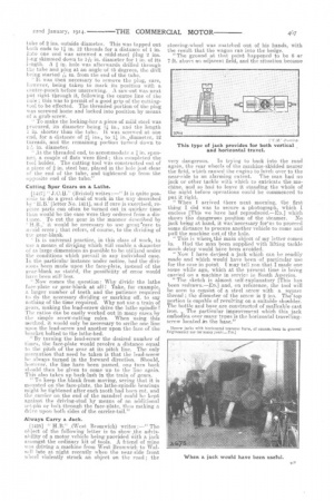
" Now I have devised a jack which can be readily made and which would have been ofparticular use for the case in point. I may tell you that I made one some while ago, which at the present time is being carried on a machine in service in South America.
"The sketch is almost self-explanatory [This has been redrawn.—En.] .and, on reference, the tool will be seen to consist of a steel screw with a square thread ; the diameter of the screw is 2 ins. The'top portion is capable of revolving on a suitable shoulder. The bottle and ba-se are constructed of malleable cast iron. „ The particular improvement which this jack embodies over many types is the horizontal travelling
screw located thebase."
[Screw jacks with horizontal traverse have, of courae, been in general Engineering use for ruany years—En.)