


OIL ENGINE HAS NO INJECTION PUMP
Page 58
If you've noticed an error in this article please click here to report it so we can fix it.
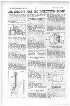
PATENT No. 664,175, shows a compression-ignition engine which needs no injection pump. The patentee, R. L'Orange, 51, ,Boulevard s St. Germain, Paris, states that the scheme is particularly suitable for small highspeed oil engines.
The principle of the scheme is to burn a small portion of the fuel charge, and to use the heat and pressure thus generated to blow the rest of the fuel into the combustion space. The drawing shows a practical layout as used in a four-stroke engine.
The fuel arrives under light pressure via pipe 1 and flows past a one-way valve into a small by-pass passage (2), its arrival being assisted by the suction of the intake stroke. On the compression stroke, part of the air is forced through a tapering passage (3) into a small chamber (4) which may contain a heater plug (5).
As the air rushes through the taper bore, it draws with it a small quantity of the fuel stored in the by-pass and atomizes it so that when the compression reaches igniting point, the combustion starts in the small chamber. The resulting pressure rise immediately reverses the air-flow and blows the remainder of the fuel into the main combustion space in the piston crown, and full burning then occurs.
By suitable dimensioning, the ignition chamber is made to burn from 3 to 10 per cent, of the total full-load fuel, and is aimed at creating a pressure of 100 atmospheres. Thc patent also shows a more simple design for use with two-stroke engines., DAIMLER-BENZ INDEPENDENT SUSPENSION SYSTEM THE latest practice in •independent suspension systems of the swinginglink type is disclosed in patent No. 663,448, which comes from DaimlerBenz A.G., Stuttgart-Untertiirkheim, Germany. The basis of the scheme is the location of the shock-absorber; this is placed inside the main helical suspension spring.
In the drawing, the stub-axle (I) is carried by upper and lower pairs of links (2.and 3). The upper links pivot at 4, the lower ones at a more inboard point (5). The whole assembly can rock slightly about a rubber-bushed pivot pin (6), the motion being restrained by rubber buffers embracing an inwardly extending arm (7). The main spring rests upon the lower pair of links and at the top is resisted by a bellhousing (8) which swings about the upper pivot. The hydraulic shockabsorber (9) lies inside the spring, the upper part being bolted to the bellhousing via rubber washers (10), whilst the lower end is hinged.
IMPROVEMENTS IN BEARING STRIP
PATENT No. 664,426, comes from W. Tait and the Glacier Metal Co.. Ltd., 368, Ealing Road, Wembley, and shows an improved design of prefabricated strip for use in the manufacture of bearings, such as big-ends and the like. The scheme described uses a copper or aluminium-alloy backing strip, with spaced inserts of lead-tin or tin-zinc alloy.
The drawing shows (left) the strip as producedl in the flat form. The backing strip (1) is regularly grooved as shown at 2 and the grooves are filled with the tin alloy. The strip is next bent into the circular form (3), which has the effect of dovetailing the grooves slightly and so pinching the inserts.
They are thus mechanically gripped in addition to the metallurgical adhesion. The grooves are actually quite small, being only 0.005 in. deep and the same in width.
A TAILBOARD CLAMPING DEVICE
FROM Vauxhall Motors, Ltd., Luton. comes patent No. 663,792, which shows an improved latch mechanism intended for use with-the tailboard of a -lorry. The 'device would be particti
darly applicable to vehicles carrying loose or semi-liquid loads where a sealed tailboard becomes essential.
The drawing shows the tailboard, hinged at its upper point (1) and fitted , with the improved latch at the bottom. Across the bottom of the body runs a rotary cross-shaft (2) fitted with a handle (3). A number of cams (4) are attached to the body, and they can be worked by the rotary cross-shaft. The lever mechanism (5) is of the toggle variety, which, when moved over °dead centre, gives a positive lock. The open position of the tailboard is shown in the chainline drawing.
MOTOR MOUNTING FOR A BATTERY-ELECTRIC
I N battery-electric vehicles, in which
the motor is mounted on the frame. some form of universal joint is needed to allow for axle movement, if excessive wear is to be avoided. A scheme for mounting the motor wholly on the axle-casing, so as to simplify the drive, is shown in patent No. 663,238, by G. and C. Haig, 49a, Thames Road, London, W.4.
The motor .(1) is flanged on to the back-axle at one end (2) and overhangs in a forward direction. The weight is supported by a tension-rod (3), which is anchored to an arched member (4) bridging the axle, and bolted to the casing. The whole assembly thus moves as a unit during spring deflections, and local stresses are avoided.
METAL INSERTS IN RUBBER TYRES
ARUBBER tyre having metal insertS consisting of coil springs is covered in patent No. 663,347, from Harold E. Kimes Corporation, Chicago, Illinois, U.S.A. Aimed at giving better wearing properties, the tyre is constructed in such a manner that the coils soon break up into small pieees during running.