


Ball-bearing Big-ends
Page 58
If you've noticed an error in this article please click here to report it so we can fix it.
BALL bearings have been used for the main journals of crankshafts, but seldom for big-end bearings, owing to the difficulty of assembly. A new type of crankshaft on which hall-bearings can be more conveniently used, is disclosed in patent No. 642,774, by the Motor Car Works National Corporation, Prague, Czechoslovakia.
In this design, a crankpin and two webs form a separate unit, as shown at I. The shape adopted enables the big-end bearings (2) to he threaded over the webs during assembly. Several such units can be bolted together to form a complete crankshaft, alignment being ensured by circular spigots (3), whilst the torsional stresses are taken by keys (4), fitting in corresponding keyways (5). The main roller-bearings are fitted to discs on the webs as shown at 6. No mention is made of means for locating the big-end.
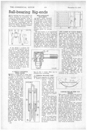
A USEFUL UNIVERSAL DRILL GUIDE
universal guide, t h e patentee being T. Flory; 5, Manor House, Earls Avenue, Folkestone.
Referring to the drawing, the drill (1) is guided by a sleeve (2) which is free' to revolve and slide in a housing (3), being mounted on roller bearings (4). The end•of the guide is shaped to suit the work, a V-shape (5) being shown for use with round work. The whole unit is mounted in the drilling machine, and all revolves except the guide, which stands still and gives an adequate location close to the work.
A40
SELF-ADJUSTING BALL-JOINT
/1\ BALL AND SOCKET IA joint which takes up slack as it develops, is the subject of patent No. 642,487, which emanates from I. Lind, and Alford and Alder (Engineers), Ltd., Deacon Street, London, S.E.17. The scheme is intended chiefly for steering joints.
The ball member is of conventional form, except that it has a flat on the top. The housing contains a stationary half-socket (I) and a similar upper half (2) which screws into the housing The adjustment is performed by the automatic screwing-in of this ring which is lightly loaded into a closing direction by a flat spiral spring (3), one end of which is tucked into the ring, and the other into the casing. Differing numbers of spring-holes are drilled in ring and cas
ing, so that a vernier effect can be obtained when assembling.
A VEHICLE HEATING UNIT
'THE latest suggestion for vehicle heaters is shown in patent No.
' 642,352, which comes from the Clayton Dewandre Co., Ltd., and others, Titanic Works, Lincoln. The present design is aimed at providing a compact . unit which can be accommodated under one of the seats of a passenger vehicle.
The drawing shows the layout of the unit, which comprises an electrically driven fan (1) which draws in air from end 2 and blows it over a nest of pipes (3) fitted with coils of wire to give added radiating 'surface. The warmed air is discharged from the lefthand end. The coiled piping is connected to the cooling system of the engine.
A fan of small power can be used, whilst the heating capacity is large for the space occupied by the heater.
THE LATEST IN VALVE DESIGN
PATE NI: No. 642,768 conies from the Ford Motor Co., Ltd., 88, Regent Street, London, W.1, and deals with the manufacture of high-duty valves. Hitherto, the best valves have been made of austenitic steel of the 18/8 type to withstand the high temperature and erosive action of the gases. This steel, being comparatively soft, requires hard-facing on the seat, usually Stellite, applied by gas-welding.
The application of this hard facing is a lengthy and highly skilled process, and the object of the present scheme is to speed up production by fitting a ready-made ring of Stellite, attached to the valve by brazing.
The main body of the valve is precision-cast by the lost-wax process, and the Stellite ring is also cast, but ground in the bore to suit the taper on the valve-head. The two units are then copperbrazed together in a reducing atmosphere, and kept at a high temperature until all the copper has diffused into the austenitic body. The valve face is machined in the ordinary way.
CORNER PILLAR FOR VAN BODIES
To enable a van body to be provided with rounded corners, without at the same time sacrificing rigidity, is the aim of a scheme shown in patent No. 642,347, by R. Neaverson, 49, Westfield Road, Leicester.
The drawing shows the proposed pillar in horizontal section. The bodywork is attached to specially shaped channel members (1) fitted with tailpieces (2); these members are preferably in the form of extrusions. At spaced heights, the channels are united by traylike pressed members (3). The inner and outer skins (4 and 5) are attaChed to the edges of the trays, and the enclosed space may be filled with lagging if desired. Rivets are mentioned as a means for joining the parts. The system could, of course, be adapted to other forms of fabrication.