


Patents Completed.
Page 18
If you've noticed an error in this article please click here to report it so we can fix it.
Complete specifications of the following patents will be sent to any address in the United Kingdom upon receipt of eightpence per copy at the Sale Branch, Patent Office, Holborn, W.C.
GEARCASE FOR MOTOR-PLOUGH WHEELS AND THE LIKE.—Stock.— No. 19,942/1910, dated, under Convention, 30th September, 1909.—This invention relates to gearcases for the wheels of self-propelled vehicles, more particularly motor ploughs or the like, in which the gear mounted on the driving wheels is liable to be damaged by the admission of dust and grit. The hubs of the driving wheels are mounted SO as to rotate independently on axles mounted on the frame of the vehicle. The driving wheels have connected to them internally-toothed gears, with which mesh pinions driven by the motor. Each toothed ring is protected against penetration of dust and the like on the outside by means of a disc secured to the wheel, and the inner sides of the rings are similarly protected by means of discs mounted on the axle. This inner disc is provided with an outwardly•directed flange to which is secured a packing ring of felt or like material, which hears against the toothed ring, thus enclosing the driving gear on the inner side 30 far as possible. According to this invention, there is fitted to this wheel an inclined deflector ring, which shields the joint between the inner disc and the toothed wheel. This is a conical ring tapering towards the outside of the wheel, and any duet or earth dropping from the upper parts of the wheel is thrown clear of the gearing. Inside this ring is fitted a second deflector ring tapering in the other direction. The free edge of the second ring extends to within a. very short distance of the inner edge of the outer ring, so that only a email gap is left between the two in which particles of earth and grit can lodge. Any particles, which, however, do get in over the second deflector ring, fail on to the outside of the toothed ring and do not get into the driving gear of the wheel, and as the wheel turns and they approach the lower side, they fall out of the second deflector ring on to the ground.
ROAD WHEELS. — Rudd. — No. 27,480, dated 25th November. 1909.—This invention relates to that kind of wheel in which a wood feline is inserted between the metal centre and the metal rim. This run may form the foundation for a robber or other tire, or it may be an ordinary metal tread. The wheel centre is formed of metal, and has attached to it a cylindrical seating rim. On one side of this rim is an integral flange extending
radially outward. The feriae is bolted to this flange towards its outer edge, and the wedge ring is inserted between the felloe and the rim. This ring is drawn towards the flange by bolts. When the ring is drawn in by these bolts, the felloe is expanded, but, owing to the flange, it cannot move axially. The wedge ring extends across nearly the whole width of the felloe, leaving only sufficient space to allow adjustment, so that the feline is adequately supported across its width. It will be seen also that, by bolting the felloe to the flange, the creeping of the felloe and rim round the wheel centre, which sometimes occurs, is entirely prevented. The bolts for tightening up the wedge ring are conveniently situated for access, so that the expansion of the tire may be taken up very readily without any axial movement of the tire and felloe.
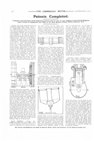
ACETYLENE GENERATORS. — Byrne and Another.—No. 9,249, dated 16th April, 1910.—This invention relateR to acetylene-gas generators, more especially those employed for lamps for motor road vehicles. It has for its object to provide an improved form in which the carbide holder is freely mounted within the generator and is adapted to oscillate under the action of the vibrations of the vehicle, and thus facilitate the falling away from the holder of the spent carbide. The generator comprises an ordinary form of gas chamber, with its superimposed water chamber which is not
shown in the drawing. On the base of the gas chamber a central stem is secured, provided at its upper end with a cup-like socket in which can rest central bearings connected to time underside of the perforated carbide holder. It is stated that a cylindrical shape for the gas chamber and carbide holder is preferable, and sufficient clearance is left between the two parts to allow the carbide holder to rock in any direction. When the vehicle is in motion, the vibration causes the holder to oscillate and the spent carbide falls to the bottom of the gas chamber. When desired, a rubber ring or similar device may be fitted round the top of the carbide holder to eliminate any noise due to contact between the two vessels. An alternative arrangement is described in which the holder is suspended by a spherical ball joint from the bottom of the water chamber and hangs inside the gas chamber.
VALVES.—Marks (McKinnon).—No. 26,576. dated 16th November, 1909,— This invention relates to valves for iiiternal-eornbustion engines of the type in
which the pressure of the gases is shut off from the inlet and exhaust ports of the engine during the compression and explosion strokes of the motor, leaving to the valve system employed only the duty of closing the exhaust port during the suction stroke and of closing the inlet port during the exhaust stroke. rn the combustion chamber a simple sleeve without ports is fitted to have a short reciprocating motion to cover and uncover the inlet and exhaust ports. This sleeve is reciprocated by a crank driven from the main shaft. The same crank also serves to operate the valves which are shown as being of the °Miss type, although any other type may be used. The sleeve may be arranged with ports, or alternatively it may be outside the combustion chamber.