


Supercharging System with Mechanical and Exhaust Blowers
Page 42
If you've noticed an error in this article please click here to report it so we can fix it.
ALTHOUGH supercharging has not yet been applied to standard road vehicles, its use is widespread on the larger size of oil engine. Patent No 537,780 comes from one of the leading authorities on the subject, A. Buckle 20, Salstrasse, Winterthur, Switzerland, who discloses a novel practice.
The drawing shows a large six-Cylindared vehicle-type engine equipped with the forced-induction arrangements. These consist of two air blowers, one (4) driven mechanically from the engine, and the other (2) powered by an exhaust-gas turbine (1). Both deliver air into the intake chamber (6) but the engine-driven one is used for starting and slow running, whilst the exhaust-driven ode takes over at higher loads when there is sufficient energy available in the exhaust gases.
A feature of the invention is the provision of automatic flap-valves (5) in the conduit of the shaft-driven blower. These allow the latter to supply air to the chamber (6) but prevents a backflow when the exhaust-driven 'blower creates a higher pressure: 'In these circumstances, the air output from blower 4 is delivered to the upper pump via pipe 3 and this provides two-stage compression at high loads.
ANOTHER WIDE-ANGULARITY UNIVERSAL JOINT
AN improved form of the universal joint which was described in our issue dated August 1 and is expressly devised for transinitting the drive to steerable wheels, is shown.' in patent No. 5.37,805 by Hardy, Spicer ,and Co., Ltd., and T. ',Green, both of Birth Road, Wilton, Birmingham. • This new design, which replaces the earlier one, and of which it is a modification, is notable for the considerable maximum angle of working, the angular velocity transmitted remaining constant up to a deflection of as much as 40 degrees..
Comprising the joint are -the twci shaft elements and an intermediate member of the sliding mortise-andtenon tpe. One shaft-end carries the mortise piece (2) which is pivoted to it by a pin (I), whilst the tenon. piece (4) is similarly pivoted on the other shaft by pin 3. in the position depicted in the lower drawing the two pin joints share the angle of deflection,, as shown by the axial' lines, whilst in the position the joint assumes 90, degrees of rotation later, the sliding unit looks after all the deflection.
The joint is claimed to be robust, and easy to manufacture, whilst durability Is assured by the use of needlerollers around the pivot pins, these being housed in the jaws of the two intermediate pieces and embracing the ends of the pins, the latter being a tight fit at their mid portions.
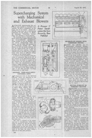
A32 SWASH-PLATE ENGINE WITH CUSHIONED PISTONS DATENT No, 537,734, by F. 1 lelannerstedt, 1.31vsunda, Sweden, discloses' details of a awash-plate engine in which thepistons m'eet a resilient cushion gt the outer end of the stroke. . The aim is to reduce the stresses on the wobble-plate by absorbing some of the energy of the firing stroke and returning it during the compression stroke.
The upper part of a section view of a six-cylindered engine is depicted. Each cylinder contairie opposed pistons (3 and 4) operated by a pair of wobblecranks (1 and 2) via an armed disc and ; universal gudgeon joints (5). • Connected to each piston is an additional piston (6) moving in unison, and working in a closed cylinder (7).
This forms the resilient opposition to the power stroke, and by its use it is claimed that the ,maximum and minimum stresses on the crankshaft are reduced to only 15 per cent, deviation
from the mean value. The space under the piston (a) is used for charging an scavenging the engine.
BETTER STABILITY IN FOR ESTR Y TRACTOR
DESIGNED, as is customary, L./for dragging large logs along .
the ground, and later for loading and towing the trailer carrying them, a forestry tractor is shown in patent No. 536,866, by J. Fielding, Capel . Dinas, Chapel Street, Anglesey. The patented features include 'means for facilitating steering when towing a trailer, and for preventing the tractor from rearing into the air should an excessive load be encountered during the operation of timber winching.
According to known practice there is a geared-down cable drum (2) for hauling the logs, during which operation the tractor is held stationary by means of a pivoted anchoring strake (1) embedded 'in the ground.
The front of the vehicle, however, is provided with a ballast container (5) -which an be loaded to minimize the risk oflifting, whilst the wheelbase is lengthened by moving the front axle from its' usual position (3) to a more forward point (4). The object of this is to improve the steering adtion when the vehicle is used in conjunction with a trailer.