


HINTS ON MAINTENANCE.
Page 32
Page 33
If you've noticed an error in this article please click here to report it so we can fix it.
How to Get the Best Out of a Vehicle, to Secure Reliability and to Avoid Trouble.
CONTRIBUTIONS are invited for this page from fleet managers, drivers, garage foremen, and mechanics, works staff and draughtsmen, and will be paid for on a generous scale. Every system, make, and type of commercial motor vehicle will be dealt with, and the matter should be written with a view to the disclosure of workshop and garage practice in the maintenance of a vehicle—practices which, whilst they may be quite normal, are peculiar to the particular vehicle and may not be generally known to those responsible for its running. Expedients and suggestions for overcoming roadside and other troubles are covered in the following page, dealing with letters from our driver and mechanic readers. Communications should be addressed to "The Editor, The Commercial Motor, 7-15, Rosebery Avenue, London, E.C.1."
252.—Preventing the Loss of Radiator Caps.
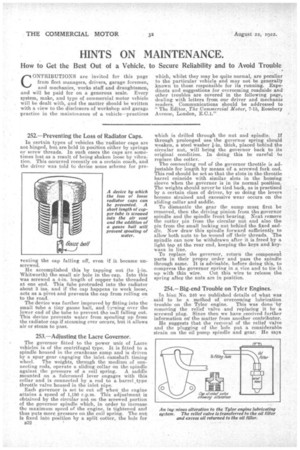
In certain types of vehicles the radiator caps are not hinged, but are held in position either by springs or screw threads. In such eases the caps are sometimes lost as a result of being shaken loose by vibration. This occurred recently on a certain coach, and the driver was told to devise some scheme for pre
venting the cap falling off, even if it became unscrewed.
He accomplished this by tapping out (to 1-in. Whitworth) the small air hole in the cap. Into this was screwed a 4-in. length of copper tube threaded at one end. This tube protruded into the radiator about 3 ins, and if the cap happens to work loose, acts as a pivot and prevents the cap from rolling on to the road.
The device was further improved by fitting into the small tube a tiny gauze ball, and taaning over the lower end of the tube to prevent the 'nail falling out. This device prevents wailer from spouting up from the radiator cap if steaming ever ocenrs, but it allows air or steam to pass.
253.—Adjusting the Lacre Governor.
The governor fitted to the power unit of Lacre vehicles is of the centrifugal type. It is fitted to a spindle housed in the crankcase sump and is driven by 'a spur gear engaging the inlet camshaft timing wheel. The weights, through the medium of connecting rods, operate a sliding collar on the spindle against the pressure of a coil spring. A saddle mounted on a fulcrumed lever engages with this collar and is connected by a rod to a barrel _type throttle valve housed in the inlet pipe.
Each governor is set to cut off when the engine attains a speed of 1,150 r.p.m. This adjustment is obtained by the crireular nut on the screwed portion of the governor spindle which, in order to increase the maximum speed of the engine, is tightened and thus puts more pressure on.the coil spring. The rrut is fixed into position by a split cotter, the hole for
B32., which is drilled through the nut and spindle. If
through prolonged use the governor spring should weaken, a steel washer 4-in. thick, placed behind the circular nut, will bring the governor back to its original condition. In doing this be careful to replace the cotter.
The connecting rod of the governor throttle is adjustable for length by means of a screwed fork end. This rod should be set so that the slots in the throttle barrel coincide with similar slots in the housing sleeve when the governor is in its normal position. The weights should never be tied back, as is practised by a certain class of driver, by so doing the levers become strained and excessive wear occurs on the sliding collar and saddle.
To dismantle the gear the sump must first be removed, then the driving pinion from tho governor spindle and the spindle front bearing. Next remove the cotter pin from the circular nut and also the pin from the small locking nut behind the fixed saddle. Now draw this spindle forward sufficiently to allow both nuts to be wound off their threads. The spindle can now be withdrawn after it is freed by a light tap at the rear end, keeping the keys and keyways in line.
To replace the governor, return the component parts in their proper order and pass the spindle through same. It is advisable, before doing this, to compress the governor spring in a vice and to tie it up with thin wire. Out this wire to release the spring aftet the nuts are in position.
254.—Big-end Trouble on Tyler Engines.
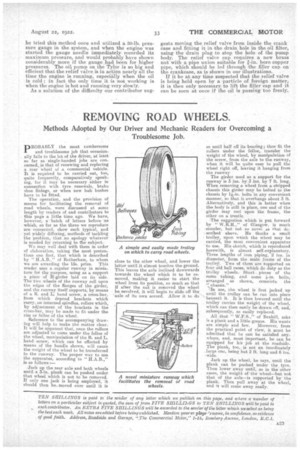
In hint No. 246 we published details of what was said to be a method of overcoming lubrication trouble on the Tylor engine. This was done 'by removing the relief valve and replacing it by screwed plug. Since then we have received further information on the matter from another contributor.
He suggests that the removal of the relief Valve and the plugging of the hole put a considerable strain on the oil pump spindle and gear. He says he tried this method once and utilized a 30-lb. pressure gauge in the system, and when the engine was started the gauge needle immediately recorded its maximum pressure, and would probably have shown considerably more if the gauge had been for higher pressures. The oil, pump on the Tyler is so big and efficient that the relief valve is in action nearly all the time the engine is running, especially when the oil is cold ; in fact the only time it is not working is when the engine is hot and running very slowly. As a solution of the difficulty our contributor sug gests moving the relief valve from inside the crank case and fitting it in the drain hole in the oil filter, using the drain plug to stop the hole of the pump body. The relief valve cap requires a new brass nut with a pipe union suitable for 1-in. bore copper pipe, which should be led through the filler cap on the crankcase, as is shown in our illustrations.
If it be at any time suspected that the relief valve is being held open by a particle of foreign matter, it is then only necessary to lift the filler cap and it can be seen at once if the oil is passing too freely.