


Patents Completed.
Page 20
If you've noticed an error in this article please click here to report it so we can fix it.
Complete specifications of the following patents will be sent to any address in the United Kingdom by the Sale Branch, Patent Office, Holborn, W.C., upon receipt of eightpence per copy.
A Tire Retainer.
A. fluckland, No. 16,326, dated 15th July. 1911.—The tire fixer described in this specification is intended to be used in connection with tires which arc filled with some rubber-like substance. The fixer is intended to hold the tire in place while the filling is being inserted, and also to retain the filled tire on its wheel.
As shown in the figure, the fixer comprises a metal band, the ends of which overlap. Slots are provided in the ends so that they may slide past each other. and also past a fixing bolt when the hand is being tightened up. To tighten thy band, a flexible tie such as a piece of wire rope is knotted at one end to one of the ends of the band. The rope is passed through the bolt-hole and pulled by some suitable tool to draw the ends of the band together, the end of the slot in that end of the band to which the rope is not applied being in engagement with the bolt. When the rope has been sufficiently tightened, it is secured in place by a nut on the bolt which may he provided with a special tightening flange for this per. pose. The invention is shown, in the figure, applied to a wheel with wooden felloes, but in a modified arrangement it is applied to a wheel having a metal rim only.
A Complicated Suspension.
A. F. Sadoux, No. 18,229, dated 6th January, 1911.—To avoid the necessity of rubber tires, the engine and all its accessories are mounted on an auxiliary chassis which is spring-supported on the principal chassis. The main frame is
provided with ordinary leaf-springs at each side, which carry the crossbars : the auxiliary chassis rests on these crossbars to which a reasonable amount of play is allowed. To prevent excessive oscillation, the auxiliary chassis is tied to the main frame at each end by an elastic connection which conveniently consists of helical springs in compression.
Another Splashguard.
S. I. Hitchcock, No. 20,839, dated 21st September, 1911.—To avoid side splashing of mud by motor vehicles, the annular mudguard shown in the figure is applied
to the outside, or to both sides of the vehicle wheel. In the form illustrated the mudguard ring is secured to the hub by radially-arranged springs, and these prevent damage to the mudguard if the vehicle should run on to the herb of the pavement, or if the tire should become punctured Shcck-absorbing Springs.
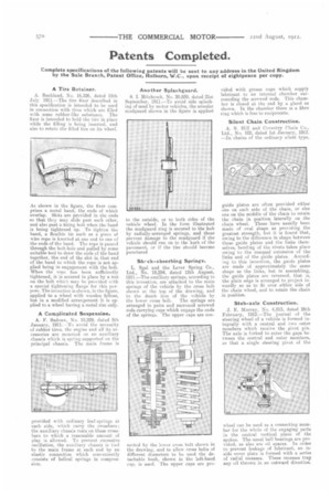
L. Sgal and the Lever Spring Co., Ltd., No. 18,294, dated 12th August, 1911.—The auxiliary springs, according to this invention, are attached to the main springs of the vehicle by the cross bolt shown at the top of the drawing, and to the dumb iron of the vehicle by the lower cross bolt. The springs are arranged in pairs and surround screwed rods carrying caps which engage the ends of the springs. The upper caps are con nected by the lower cross bolt shown in the drawing, and to allow cross bolts of different diameters to be used the detachable bush, shown in the left-hand cap, is used. The upper caps are pro vided with grease cups which supply lubricant to an internal chamber surrounding the screwed rods. This chamber is closed at the end by a gland as shown. In the chamber there is a fibre ring which is free to reciprocate.
Silent Chain Construction.
A. S. Hill and Coventry Chain Co., Ltd., No. 102, dated 15t January, 1912. —In chains of the ordinary silent type,
guide plates are often provided either one on each side of the chain, or else one on the middle of the chain to retain the chain in position laterally on the chain wheel. These have usually been made of oval shape as providing the greatest strength, but it is found that, owing to the difference in shape between these guide plates and the links themselves, bending of the rivets takes place owing to the unequal extension of the links and of the guide plates. According to this invention, the guide plates are made of approximately the same shape as the links, but in assembling, the guide plates are reversed, that :s, the plain edge is arranged to project inwardly so as to fit over either side of the chain wheel, and to retain the chain in position.
Stub-axle Construction.
J. E. Murray, No. 4,813, dated 26th February, 1912.—The journal of the steering wheel of a vehicle is formed integrally with a central and two outer members which receive the pivot pin. The axle is forked to enter the gaps between the central and outer members, so that a single steering pivot of the wheel can be used as a connecting member for the whole of the engaging parts in the central vertical plane of the spokes. The usual ball bearings are provided, as also are oil spaces. In order to prevent leakage of lubricant, an inside cover plate is formed with a series of radial recesses. These recesses trap any oil thrown in an outward direction.