


Electric Vaporizer for Starting Oil Engines
Page 66
If you've noticed an error in this article please click here to report it so we can fix it.
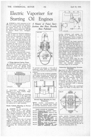
ASCHEME in which operation of the starter switch causes the vaporization of a small amount of fuel before the starter motor can be energized, forms the subject of patent No. 481,468 by Robert Bosch A.G., Stuttgart, Germany.
The arrangement disclosed employs a length of pipe' (1) which is insulated at one end and included in the startermotor circuit. The pipe is filled with oil fuel, and upon the closure of the switch (3) is immediately heated by the flow of current. A bimetallic strip (2) alongside the pipe serves as a thermostatic control, the points (5) of which close the starter-motor circuit so soon as the tube reaches vaporizing temperature. A second switch (4) is provided for restarting without heating. .
By this means vaporized fuel is introduced into the air-induction pipe. The scheme is claimed to effect starting with a mmum of time and current, as the first few piston strokes fill the cylinders with combustible vapour.
A Wedge-tightened Spring Clamp. A LTHOUGH intended primarily for tArailway work, the spring clamp shown in patent No. 481,925 would doubtless be of advantage in any type
of heavy-duty leaf-spring. The patentee is D. Yates, 0.B.E., Highclere, Chislehurst, Kent.
The scheme comprises an encircling welded-up ring (2), in the upper end of which is inserted a pair of wedges (3). A U-bolt (1) surrounds the upper wedge, and by tightening the nuts it becomes a simple matter to compress • the spring into a rigid assembly.
Elastic Cylinder Mounting to Prevent Knock.
ASCHEME for the prevention of " Diesel knock " and similar shocks is shown in patent No. 481,339 by E.• Bugatti, Molsheim, France. The basic of the invention is the use of resilient buffers between the cylinder and the crankcase.
The drawing shows one of several suggested schemes; in this case the cylinder is provided with a flange (3) which is clamped between rubber rings surrounding the holding-down bolts. a36 To prevent oil leakage, a boot (2) is employed, whilst there are abutments ' (1) to limit excessive movement of the cylinder.
The drive to the overhead camshaft, which must, of course, be unaffected by the cylinder displacement, forms the subject of another patent, No. 481,340. duction methods, and patent No. 481,534, by F. Weakley, 71, Bowyer Road, Birmingham, shows a design in which all-steel construction is used for these components.
In this scheme the frame members carry pairs of upstanding brackets (3) which are clamped to the frame at the lower end, and united at the top by welding to channel-section ergss-inemhers (1). The channel is Oared in the open-top position, and is provided with upper flanges for the attachment of the floor-boards. Each cross-member projects slightly beyond the body to form lugs (2); these act as hinges for the drop-sides of the body.
The inventor states that by this means a large variety of bodies ,can be assembled from stock components, whilst the finished structure is extremely light for its strength.
Enhancing Injection-pump Governor Reliability.
PATENT No. 981,271, fiord H. Dunn and Simms Motor Units, Ltd., Oak Lane, London, N.2, deals with refinements to the governor mechanism of an injection pump. The specification states that the cross-pin, uniting the two bell-cranks used in such mechanism, is apt to work loose and to damage the adjacent parts, and the patent is concerned with a retaining device for this pin.
The drawing shows the centrifugal weights (1) which, as they Move out wards, operate U-shaped bell-cranks (2). The inner ends are pivoted to the central control by a cross-pin (3), and to avoid weakening this pin by shouldering or drilling, it is proposed to prevent endwise movement by the use of a pair of retaining plates (4).