


Suction-operated Traffic Indicators
Page 58
If you've noticed an error in this article please click here to report it so we can fix it.
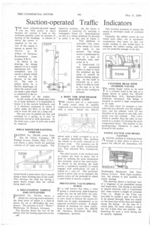
THE usual solenoid-operated signal operative position. On the frame is arm has little power to spare mounted a turntable (1) carrying a because the current is kept at the rectangular frame (2). Superimposed minimum possible value on account of on this is a tilting platform (3) pivoted heating of the windings. A scheme in at point 4 at one end of frame 2.
which the power is supplied by the suction of the engine is shown in patent No. 705,575, by W. O'Shei, 63 Fairacres, Roehampton Lane, London, S.W.15.
As shown in the drawing, the design appears to be a sound mechanical job. The semaphore arm (1) carries a pinion which is revolved by the descent of the ratk (2). The rack is pulled down by a flexible diaphragm (3) when the control cock (4) opens a pipe which is connected to the in take manifold of the engine.
As the casing of the diaphragm must be of large diameter, it is impossible to house it in the narrow bodywork, and it is therefore proposed to locate it either under the floor or on the roof and to work the rack via a long rod.
The arm may be pulled one way and returned by a spring, or it may be positively moved in both directions. In the latter case, a pair of pull-rods would be required.
SPRAY BOOTH FOR PAINTING VEHICLES
PATENT No. 706,600 comes from The De Vilbiss Company, 300 Phillips Avenue, Toledo, Ohio, U.S.A., and shows a spray booth for painting vehicles of all types and lengths. The
actual booth is quite short, but it travels along a track forming part of the outfit. This obviates the need for having a spray booth longer than the vehicle being dealt with.
A SELF-LOADING VEHICLE FOR CONTAINERS
PATENT No. 705,916, shows a vehicle for carrying load-containers, the chief point of which is a built-in device for on or off-loading the containers. The patentee is A.G. "Weser," Werfstrasse 18, Bremen, Germany.
The drawing shows the rear of the vehicle with the loading apparatus in the This platform Is provided with extensible ramps (5) which can reach to the ground. The tilting action is per6ormed by one or a pair of hydraulic rams indicated at 6.
A hand-winch (7) and its associated cables is used to haul the container up the ramp or control its descent during unloading. As the outfit is mounted on a turntable it is able to work at the mar or at the sides as the conditions demand.
A BODY FOR SEMI-TRAILER TRACTIVE UNITS
THE tractive unit of a semi-trailer outfit could often be usefully employed as a load carrier were it fitted with a body. Patent No. 690,541
shows such a body arranged so as to be quickly detachable, thus enabling the vehicle to be easily restored to its normal work. The patentees are B. Farrington, and Hands (Letchworth) Ltd., New Icknield Way, Letchworth, Herts.
The chief novelty is the method used to anchor the body in place; this is done by utilizing the same mechanism that normally receives the semi-trailer. As shown in the drawing, the body carries a cylindrical member (I) which engages with guide-plates (2) and is locked by a cam (3). This particular layout is given only as an example; the patent covers all the methods by which a semi-trailer is usually coupled.
PREVENTING VALVE-SPRING SURGE
iT is well known that when a valve spring is compressed, high-frequency surges can run up and down the coils, and can set up a gross 'overload. This, in turn, leads to failures the reason for which can be quite unsuspected, as no apparent overload is present. A simple method of damping out these oscillations is shown in patent No. 690,340 (W. Nicolson. Shrubland Old Hall, Coddenham, Ipswich).
This inventor proposes to encase the spring in envelopes made of synthetic rubber.
Normally, the rubber covers do not touch each other, but at maximum compression they meet, so that any surges tending to rise would have to compress the rubber casing, and they are not powerful enough to do this.
CYLINDER HEAD WITH OVERSIZE VALVES
enable larger valves to be used in a cylinder head is the aim of a design shown in patent No. 705,418 (Daimler-Benz A.G., Stuttgart-Untertiirkheim, Germany). The design is claimed to permit a high compression to be used.
The inlet valve (1) occupies a considerable area directly over the cylinderbore, and the exhaust valve (2) has therefore to be placed to one side, only partly over the cylinder. This valve, which is smaller than the inlet, is contained in a pocket (3) forming the main compression space. The injector or the sparking-plug, whichever is used, is located in this pocket.
FIXING CLUTCH AND BRAKE FACINGS A NOVEL method of attaching brake r't facings to their shoes is shown in patent No. 690,145 (EL Amundsen, 836
Washington Boulevard, Oak Park, Illinois, U.S.A.). With slight modification, the scheme is also suitable for clutch facings.
The drawing shows a sectional view of a fragment of an assembled facing and brake-shoe. The facing is provided at spaced intervals with a T-sectioned slot; these receive a length of extruded T-bar (I). Holes in the T-bar are provided to enable a pair of bolts (2) to be passed through; these are nutted on the inner face of the shoe and tightly clamp the facing. In the case of a clutch plate, the same scheme is used, but the T-slots then run radially. By loosening the nuts, a worn facing can be quickly replaced.