 1
1 2
2 3
3 4
4 5
5 6
6 7
7 8
8 9
9 10
10 11
11 12
12 13
13 14
14 15
15 16
16 17
17 18
18 19
19 20
20 21
21 22
22 23
23 24
24 25
25 26
26 27
27 28
28 29
29 30
30 31
31 32
32 33
33 34
34 35
35 36
36 37
37 38
38 39
39 40
40 41
41 42
42 43
43 44
44 45
45 46
46 47
47 48
48 49
49 50
50 51
51 52
52 53
53 54
54 55
55 56
56 57
57 58
58 59
59 60
60 61
61 62
62 63
63 64
64 65
65 66
66 67
67 68
68 69
69 70
70 71
71 72
72 73
73 74
74 75
75 76
76 77
77 78
78 79
79 80
80 81
81 82
82 83
83 84
84 85
85 86
86 87
87 88
88 89
89 90
90 91
91 92
92 93
93 94
94 95
95 96
96 97
97 98
98 99
99 100
100 101
101 102
102 103
103 104
104 105
105 106
106 107
107 108
108 109
109 110
110 111
111 112
112 113
113 114
114 115
115 116
116 117
117 118
118 119
119 120
120 121
121 122
122 123
123 124
124 125
125 126
126 127
127 128
128 129
129 130
130 131
131 132
132 133
133 134
134 135
135 136
136 137
137 138
138 139
139 140
140 141
141 142
142 143
143 144
144 145
145 146
146 147
147 148
148 149
149 150
150 151
151 152
152 153
153 154
154 155
155 156
156 157
157 158
158 159
159 160
160 161
161 162
162 163
163 164
164 165
165 166
166 167
167 168
168 169
169 170
170 171
171 172
172 173
173 174
174 175
175 176
176 177
177 178
178 179
179 180
180 181
181 182
182 183
183 184
184 185
185 186
186 187
187 188
188 189
189 190
190 191
191 192
192 193
193 194
194 195
195 196
196 197
197 198
198 199
199 200
200 201
201 202
202 203
203 204
204 205
205 206
206 207
207 208
208 209
209 210
210 211
211 212
212 213
213 214
214 215
215 216
216 217
217 218
218 219
219 220
220 221
221 222
222 223
223 224
224 225
225 226
226 227
227 228
228 229
229 230
230 231
231 232
232 233
233 234
234 235
235 236
236 237
237 238
238 239
239 240
240 241
241 242
242 243
243 244
244 245
245 246
246 247
247 248
248 249
249 250
250 251
251 252
252 253
253 254
254 255
255 256
256 257
257 258
258 259
259 260
260 261
261 262
262 263
263 264
264 265
265 266
266 267
267 268
268 269
269 270
270 271
271 272
272 273
273 274
274 275
275 276
276 277
277 278
278 279
279 280
280 281
281 282
282 283
283 284
284 285
285 286
286 287
287 288
288 289
289 290
290 291
291 292
292 293
293 294
294 295
295 296
296 297
297 298
298 299
299 300
300 301
301 302
302 303
303 304
304 305
305 306
306 307
307 308
308 309
309 310
310 311
311 312
312 313
313 314
314 315
315 316
316 317
317 318
318 319
319 320
320 321
321 322
322 323
323 324
324 325
325 326
326 327
327 328
328 329
329 330
330 FODENS
Page 125
Page 126
Page 127
If you've noticed an error in this article please click here to report it so we can fix it.
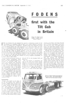
first with the Tilt Cab in Britain
FHE lirst British tilt cab designed for quantity production as part of the' ipecification of a standard range of heavy-duty goods vehicles is unveiled today by Fodens, Ltd., on Stand 87. Weighing little more than the existing oden non-tilting plastics cab, and expected to cost little more either, the new esign is a successful answer to the British "dismal Jimmys " who for years Ave said that to build a tilt cab along the American linei would incur weight id cost penalties which no British operator would be prepared to accept. ollowing the visit of the Technical Editor to the U.S.A. over five years ago, hc Coinfnercial Motor has frequently emphasized the advantages to be gained .om the use of a tilt cab: now British operators will be able to see for them:Ives whether they will find this method of giving complete accessibility to ie power unit to their liking.
-the Foden tilt cab fits into a policy ot mplified chassis maintenance which odens, Ltd., have embarked upon in an -ideavour to overcome rising m a innance costs resulting from increasing .bour charges. The cab is only part of le story, for the eight-wheeled chassis 1 which it can be seen on the Fodens and incorporates also a two-spring :vie which needs no lubrication what)eycr—except in the axle pots, of course. his bogie is completely new, as is also le seven-speed gearbox with which this lassis is fitted, a gearbox which will rentually supplant the Foden 12-speed ansmission which has been a feature
this manufacturer's vehicles for a msiclera hie time.
orerunner Mention was made in our issue of xly 20 that Fodens, Ltd., would be (hibiting a vehicle with a tilt cab at the how, but we have not been able to give is further details of this cab—or the hicle upon which it is fitted—until ■ dav. The eight-wheeler on the Fodens and is the forerunner of a completely w range of high-performance, lowainte.nance goods vehicles, which will known as the T types and will have E prefixes when Foden engines are fitd, TX when the Gardner 6LX is instal led and TW for the Gardner 5LW and 6LW units.
The eight-wheeler is remarkable not only for the three new features already referred to, but also for its low unladen weight. the chassis-cab kerb figure being 6 tons 4 cwt. (5 tons 17 cwt. dry), giving an allowance for body and payload of 17 tons 16 cwt. Although this weight is not as low as some of the other eight wheelers at the Show, the Foden TE.6/24 has a 175-b.h.p. diesel engine, 5-ton front and 9-ton rear axles, 12-in.-deep chassis frame, and eight-wheel braking, features which give good road performance. useful strength margins and all-important safety.
Although, like the earlier Foden cab, the new tilt cab is of alt-plastics construction, it is of entirely new design and inherits no mouldings from the earlier version. The simplicity of the cab is commendable, as it consists basically of only two sections: the non-tipping driver's floor and the driver's side of the engine cowl, and the one-piece tipping section which includes also the main engine-cowl portion and the complete floor on the mate's side. There are, in fact, only three mouldings in the tipping part, these consisting of two roof mouldings (the roof is double skinned) and the remaining portion which is laid up in one piece. The fixed section of the cab is in two pieces, the right-hand side of the engine cowl being flanged and bolted to the remaining moulding. The floor itself includes a bulkhead-type panel immediately ahead of the steering column, into the top of which are inset the instruments, The forward face of this bulkhead carries the heater. The fully adjustable driver's seat is pedestal-mounted on the fixed floor, and its squab is hinged to permit the cab to be tilted. All that is necessary, however, when tilting is to fold the seat squab forward, for the steering column, pedals, gear-change and handbrake levers do not move when the cab is raised.
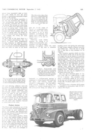
The Tilt Cab The main tilting section of the cab includes the wings on both sides, the forward-entry steps and the doors, and the complete assembly is self-supporting in that there is no main underframing, the only reinforcements being two transverse rails and two vertical pillars moulded into the front panel, timber door pillars and metal hinge plates in the area of the tilting pivots. The cab is carried on two Metaxentric eccentric rubber bushes at the front end, and these provide the hinge points, with the thicker portions of the hushes uppermost to carry the weight of the cab. These bushes are located in brackets attached to the main chassis frame, and a pair of transverse torsion bars provide the counter-balancing effect so that the call can be lifted quite easily with one hand. The rear of the cab is supported on two rubber blocks carried on an inverted-U frame bolted to the chassis side members. This bridging member carries the locking mechanism also, and in the interests of safety the lock can only be released when two controls are operated, one of which is inside the cab and the other behind the cab, on the left side of the vehicle. Thus, the cab cannot be accidentally tilted by an occupant of the cab, neither can it be lifted solely from outside.
Thick Rubber Seals
Thick rubber sealing snips are applied to the mating edges of the fixed and moving sections of the cab so that the joint is fully closed. In any case, it is considered that there should be negligible relative movement along the line of this joint. It will be seen, therefore, that the interior of the cab is more completely isolated from the engine compartment and ambient weather conditions than is usual with a heavy vehicle cab, for there are no holes at all in the driver's floor, whilst from the right-hand edge of the engine cowl to the left-hand wheel arch the moulding is unbroken and smooth. and includes the mate's-seat box, beneath which the batteries are located, and a ramped foot-rest ahead of the seat, with the engine air-cleaner lying beneath it.
No modifications to the basic chassisframe layout of any of the vehicles to which the tilt cab will be applied are necessary, and the size of the engine compartment is such that all the power units currently used by Fodens. Ltd., can be accommodated. Because of the absen of any traps or other types of apertu in the engine cowling, rapid use of a co ventional engine-oil dipstick is n possible, but this is to be overcome I the provision, as standard, of a Fran mann automatic lubricator at the rear the cylinder block: this needs topping only at long intervals (a sight-glass provided) and it automatically •ensur that the level of lubricant in the sump maintained at the correct height. T radiator filler is reached through a co ventional trap at the front of the vehic beneath the windscreen.
The double-skinned roof is formed in a ventilation duct, with two air inlets the peak immediately above the win screen and two adjustable outlets in Si cab, also above the windscreen. T quarter lights in the doors can be turn. to act as scoops, so giving addition ventilation, whilst the doors conta balanced-drop windows also. Engin compartment insulation is provided by plastics substance sprayed to .the undc side of the main cowl section, whilst Si heating equipment, which incorporat an adjustable outlet into the cab, fee two wide demister ducts, exterior clea lmess of the windscreen being eaten for by twin wipers with Trico operation.
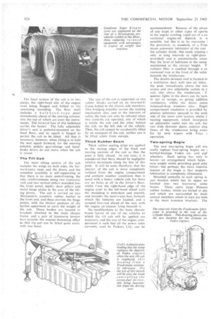
Two-spring Bogie
The new two-spring bogie will eve tually replace four-spring bogies on i• normal-haulage Foden sixand eigl. wheelers. Each spring has only tv leaves—an arrangement which helps save weight whilst providing good artic lation—but perhaps the more importa
• feature of the bogie is that susperisit lubrication is completely eliminated.
Mounted centrally to each spring is cast bracket which has its upper en. formed into two transverse conic bosses. These carry large Metacoi rubber bushes, which are bolted in pla■ and which are surrounded by math conical members which in turn are bolts to the main trunnion brackets. The ackets have inverted-U slots at their wer ends which fit over the pivot sembly. so permitting reasonably simple moval of the springs.
Lich end of the spring assemblies is ain, but has dowelled arid welded to two semi-circular steel blocks which rni cylinders extending the full width the spring. The springs are underslung, id Ihe axle tubes carry split boxes which rround the spring ends. Inside these ixes are polyurethane bushes which are -shaped and which embrace the cylinIs on the spring ends: the bushes do .1 have a constant section, being thicker the bottom, this being the loadrrying section.
On each side of the bush there is a ecially shaped polyurethane disc, the intour of which gives progressively creasing resistance to sideways moveent whilst at the same time permitting lative transverse movement between the ame and axles in order to cut down
rub and allowing sufficient inter-axle ticulation to avoid twisting the springs. Brakincand driving-torque reaction is yen by the springs combined with Lbber-buslied torque arms connected -...tween the tops of the axles and a .hint 1-section cross-member at the )gie centre-line, whilst localized frame rinsing is catered for by the provision channel-section flitch plates running side the main side members between e centre-lines of the axles.
Foden Axles 1 he 9-Ion axles themselves are of the test Foden type, incorporating pancakeaped sumps to give additional oil parity and cooling, and tapered-roller lb bearings instead of the parallel-roller tarings formerly employed.
The new seven-speed gearbox which ill replace the original Foden 12-speed tit in due course has about the same eight as the 12-speed box but a conlerably higher torque rating (given by c use of very wide low-ratio gear teeth) id has been designed to cope with the ttpitts of engines of up to at least i0 b.h.p. The ratios are arranged to give an overall range of 10 to I. in graduated steps, whilst the upper four ratios are spaced so as to give optimum performance and engine speed under all conditions likely to he met on trunk roads.
Following usual Foden practice, the casing is of ribbed aluminium-alloy construction, with ballor rollerbearings throughout, whilst the basic construction of the box is orthodox inasmuch as constant-mesh gearing is employed for third, fourth, fifth, sixth and top gears, with bottom, second and reverse by sliding gears. The box differs from normal, however, in having two lay shafts for bottom, second and reverse, this arrangement being the subject of a pending patent and giving the advantage of high torque capacity without excessive gear-wheel size. Thus the box is made into a unit that is very compact for its capacity.
The overdrive gearing which provides the top ratio is at the rear of the box and is brought into use by means of a separate air-pressure control lever mounted on the steering column. The air circuit is interlinked with a second circuit operated by a valve which is actuated when the main gear lever is in the sixth-gear position. Thus overdrive can only be used as a step-up from sixth, this arrangement preventing it being used to split the intermediate ratios. Should overdrive not be required, the box can be supplied as a six-speed direct-top unit.
The box gives forward ratios of 7.5, 4.57, 2.94, 1.86, 1.3, 1 and 0.78 to 1, with 7.5 to 1 reverse, The overdrive ratio gives a maximum speed of 57.5 m.p.h. in the case of a Foden eight-wheeler with Foden Mk. VI diesel engine and 5.75 to final drive.
The speed when a Gardner 6LX engine is installed in conjunction with 5.2 to axles is 49.5 m.p.h.