


A Variable-compression Engine
Page 62
If you've noticed an error in this article please click here to report it so we can fix it.
A VARIABLE-COMPRESSION PA engine would be ideal for varying the power output, but hitherto the mechanical difficulties have made it impracticable. A new approach to the problem is shown in patent No. 656,345,
by G. Petit, Montreuil L'Argille, Prance.
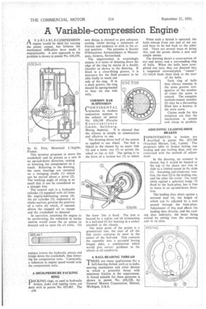
This inventor proposes to move the crankshaft and its pistons as a unit in an up-and-down direction, raising or lowering the compression as a result. Referring to the drawing, the main bearings are mounted on a swinging cradle (1) which can be moved about a pivot (2). The working angle of swing is so small that it can be considered as a straight line.
The control unit is a hydraulic 'cylinder (3) supplied with oil from the engine-lubricating pump (4). An air cylinder (5), responsive to intake suction, governs the position of a valve (6) which, if opened, allows the trapped oil to escape and the crankshaft to descend.
In operation, assuming the engine to be accelerating, the reduction in intake suction would cause the air piston to descend and so open the oil valve. Oil escapes, lowers the hydraulic piston, and brings down the crankshaft, thus lowering the compression ratio. Conversely, a reduction in engine speed would raise the compression ratio, .A HIGH-PRESSURE PACKING RING
pACKING rings, as used in hydraulic brakes, jacks and tipping rams, are dealt with in patent No. 655,467. The a36
new design is claimed to give adequate sealing, whilst having a minimum of friction and tendency to stick in the atrest position. The patentee is Societe D'Inventions Aeronautiques et Mecaniques, Geneva, Switzerland.
The improvement is surprisingly simple; it cr-nsists of thinning down the edge of the ring by means of a double chamfer as shown in the drawing. If fitted in a close-fitting groove, it is necessary for the fluid pressure to be able freely to reach one side of the ring_ If in a slack groove, the ring should be spring-loaded to bear on one side only.
TORSION BAR SUSPENSION rONTINENTAL %--..practice in modern suspension systems is the subject of patent No. 656,I9ff (Porsche Konstruktionen G.m.b.h., Sa lzbur g Morzg, Austria). It is claimed that the scheme is simple in construction and effective in use.
The drawing shows half of the system as applied to one wheel. The hub is linked to the chassis by an upper link (1) and a lower one (2) to permit the wheel to rise or fall. The spring is in the form of a torsion bar (3) to which the lower link is fixed. The hub is located by a radius rod (4) terminating in a ball-end (5) for housing in a socket attached to the chassis.
The main point of the patent is a geometrical one; the axes of all the link pivots converge to meet in the centre of the ball-end. This converts the assembly into a pyramid having hinged sides, a construction which would give correc. guidance to the wheels in all conditions.
A BALL-BEARING THREAD
THERE are many applications fin a 1 ball-bearing thread, such as in jacks, steering mechanism and other devices in which a powerful thrust with minimum friction is the requirement. A thread suitable for these purposes is shown in patent .No. 656,338,. by General Motors Corporation, Detroit, Michigan, U.S.A.
When such a thread is operated, the balls emerge from one end of the nut and have to be fed back to the other end. There are several ways ot doing this, and the patent shows a new, and simple means.
The drawing shows a cross-section of nut and screw, and a surrounding ring of balls. When the balls have completed one turn, they are directed into a tangential reversed-pitch " tunnel " (1) which leads them back to the start of the helix.
Each ring of balls thus always remains in the same groove, irrespective of the number of times the screw is rotated. The complete multiple-tunnel member (2) may be a die-casting fitted into a keyway in the male screw.
Claims made for this invention are that the mechanism is simple and cheap to produce.
ADJUSTING LEADING-SHOE BRAKES
I MPROVEMENTS in brakes are described in patent No. 655,740 (Vauxhall Motors, Ltd„ Luton). 'The proposals refer to brakes having one leading and one trailing shoe, and are concerned with the method of adjustment.
In the drawing, no actuator is shown, but it would be located at the top of the shoes, and free to slide to a limited extent in the slots (1). Assuming anti-clockwise rotation, the shoe (2) is the leading one, and the other the trailer The latter abuts against a spherical bulge ',3) fixed to the back-plate.-but is free to move in an up-and-down direction.
The leading shoe abuts against a screwed stud (4), the length of which can be adjusted by a tool passed through the back-plate. Adjustment of this stud affects the leading shoe directly, and the trail ing shoe indirectly, the latter being moved by setting over the actuating unit in its slots.