Abridgments of Interesting Patent Specifications.
Page 16

If you've noticed an error in this article please click here to report it so we can fix it.
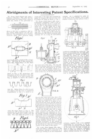
No. 18,044, dated August 19th, 1904.— Radiator.—Ilamilton.—The gills for the radiator tubes are formed from a strip of. metal (13),. which is first perforated as shown at B2, Fig. 3, projections (B3) being formed which extend into the perforations. The perforations are of uniform distances apart, these distances being equal to the pitch or depth of the corruga. lions. The strip (B) is then pressed be. tween dies, which bring it to the shape , Ws? , 4 ald
shown in Fig. 4, the projections (113) being bent out from the body of the strip in such manner as to form recesses (13I, Fig. 5) adapted to receive the radiator tube (A). Before fixing the gills in position upon a tube the strip is compressed longitudinally so that it is made to as
it) 71 sumo the shape shown in Fig. 6. The projections (B3) are thus brought close together, and make good contact with the tube. Two such strips are placed on op posite sides of the tube and connected together by tongues (B4) and are bent over to connect the strips as shown in Fig. 2.
No. 18,045, dated August x9th, tette.— Carburetter.—HamiIton.—Euel is fed to the mixing chamber (A) by a nozzle (C). Free to slide in the mixing chamber is a sleeve (CI). At the upper end of this sleeve are apertures (132) by which the interior of the sleeve may communicate with the cylinder of the engine by passage (A2). At the base of the sleeve are other apertures (133) which co-operate with openings (El) in a ring (E) surrounding
the lower end of the tube. The ring (E) lies in an annular space (A3) in ccmrnunication with the atmosphere by an inlet (Al), and can be partially rotated by a lever (E2) so that its apertures are brought more or less into, or out of, register, with those in the lower end of the sleeve (Cl). The sleeve (CI) may be raised and lowered by hand or automatically, but it will be observed that when it is raised to partially throttle the outlet (A2) the inlets for air thrisugh the orifices (10) arc correspondingly restricted, although these can be further separately controlled by the ring (P).
It will be seen that in this form of carburetter the throttle valve (B2) is operatively connected with the valve (133h which regulates the admission of air to the mixing chamber, although the movement of the valve (E) co-operating with the admission valve is separately controlled. The throttling and air admission valves are so arranged that the air entering the mixing chamber always bears a predetermined proportion to the amount of throttling, but this can be further adjusted by the second air valve (E) in direct proportion to the speed of the engine.
No. 1e,e6r, dated August 18th, Clerk and Others.—The Piston (r) of the low pressure cylinder is connected to a piston (p) working in art air compression cylinder. Air is admitted by ports (t.1) at the base of the cylinder, and a weak mixture is drawn into the cylinder from a
conduit (y) controlled by a valve (w). The charge is compressed into the high pressure cylinders (a) through passages (s) controlled by valves (t), one of these valves being always closed by the pressure of gases within that particular cylinder which will be performing its working stroke at the moment when the other cylinder is being charged. The exhaust gases pass by valves (d) into the low pressure cylinder (b). The stems of the valve (d) are made gas-tight by packing rings (dl). The high pressure cylindere are charged at a pressure considerably above that of the atmosphere with a weak mixture so that very high average pressure is obtained in the high pressure cylinders, together with a low terminal temperature for transference of the exhaust to the low-pressure cylinder, whilst at the same time the high pressure exhaust is kept at a pressure sufficiently high to enable the power to be nearly equally divided between the cylinders.


