


Space-saving Container
Page 78
If you've noticed an error in this article please click here to report it so we can fix it.
pATENT No. 840,514 covers a rotary
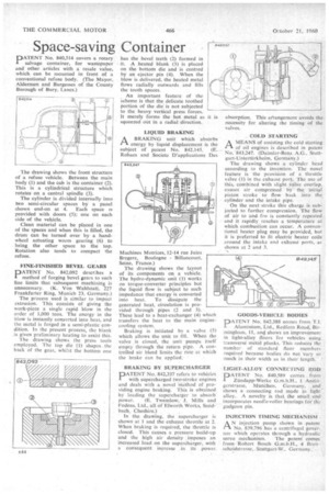
salvage container, for wastepaper and other articles with a resale value, which can be mounted in front of a conventional refuse body. (The Mayor, Aldermen and Burgesses of the County Borough-of Bury, Lancs.) The drawing shows the front structure of a refuse vehicle. Between the main body (1) and the cab is the container (2). This is a cylindrical structure which rotates on a central spindle (3).
The cylinder is divided internally into two semi-circular spaces by a panel shown end-on at 4. Each space is provided with doors (5); one on each side of the vehicle.
Clean material can be placed in one of the spaces and when this is filled, the drum can be turned over by a handwheel actuating worm gearing (6) to bring the other space to the top. Rotation also tends to compact the refuse.
FINE-FINISHED BEVEL GEARS PATENT No. 842,092 describes a method of forging bevel gears to such fine limits that subsequent machining is unnecessary. (K. Von Wahlstatl, 227 Frankfurter Ring, Munich 23, Germany.)
The process used is similar to impact extrusion. This consists of giving the work-piece a single rapid blow in the order of 1,000 tons. The energy in the blow is instantly converted into heat, and the metal is forged in a semi-plastic condition. In the present process, the blank is given preliminary heating to assist this.
The drawing shows the press tools employed. The top die (1) shapes . the back of the gear, whilst the bottom one has the bevel teeth (2) formed in it. A heated blank (3) is placed on the bottom die and is centred by an ejector pin (4). When the blow is delivered, the heated metal flows radially outwards and fills the tooth spaces.
An important feature of the scheme is that the delicate toothed portion of the die is not subjected to the heavy vertical press forces. It merely forms the hot metal as squeezed out in a radial direction.
LIQUID BRAKING ABRAKING unit which absorbs energy by liquid displacement is the subject of patent No. 842,145. (E. Roha.cs and Societe D'applications Des
Machines Motriees, 12-14 rue Jules Bregere, Boulogne Billancourt, Seine, France.) The drawing shows the layout of its components on a vehicle. The hydro-dynamic unit (1) works on torque-converter principles but the liquid flow is subject to such impedance that energy is converted into heat. To dissipate the generated heat, circulationis provided through pipes (2 and 3). These lead to a heat-exchanger (4) which transfers the heat to the main enginecooling system.
Braking is initiated by a valve (5) which allows the unit to fill. When the valve is closed, the unit pumps itself empty through the return pipe. A controlled air bleed limits the rate at which the brake can be applied.
BRAKING BY SUPERCHARGER
PATENT No. 842,337 refers to vehicles with supercharged two-stroke engines and deals with a novel method of providing engine braking. This is obtained by loading the supercharger to absorb
power. (E. Twemlow, J, Mills and Fodens, Ltd., all of Elworth Works. Sandbach, Cheshire.)
in the drawing, the supercharger is shown at 1 and the exhaust throttle at 2. When braking is required, the throttle is closed. This causes a pressure build-up and the high air density .imposes an increased load on the supercharger, with a consequent increase in its power
it is absorption. This erangernent avoids the necessity for altering the timing of the valves.
COLD STARTING
AMEANS of assisting the cold starting of oil engines is described in patent No. 843,247. (Daimler-Benz A.G., Stottgart-Untertfirkheim, Germany.) The drawing shows a cylinder head according to the invention. The novel feature is the provision of a throttle valve (1) in the exhaust port. The use of this, combined with slight valve overlap. CALISCS air compressed by the initial piston stroke to flow back into the cylinder and the intake pipe.
On the next stroke this charge is subjected to further compression. The flow of air to and fro is constantly repeated and it rapidly reaches a temperature at which combustion can occur. A conventional heater plug may be provided, but it is preferred to fit electric heater coils around the intake and exhaust ports, as shown at 2 and 3.
GOODS-VEHICLE BODIES pATENT No. 842,388 comes from Ti.
Aluminium, Ltd., Redfern Road, Birmingham, 11, and shows an improvement in light-alloy floors for vehicles using transverse Metal planks. This reduces the number of standard floor members required because bodies do not vary so much in their width as in their length.
LIGHT-ALLOY CONNECTING ROD
PATENT No. 840,589 comes from Zundapp-Werke G.m.b.H., 1 Anzingerstrasse, Murfchen, Germany, and shows a connecting rod made in light alloy. A novelty is that the small • end incorporates needle-roller bearings for the gudgeon pin.
INJECTION TIMING MECHANISM.
AN injection pump shown in patent No. 839.796 has a centrifugal governor which operates through a hydraulic
servo mechanism. The patent comes from Robert Bosch G.m.b.H.. 4 Breitscheidstrassc, .Stuttgart-W.. Germany.'