


A Novel Water Pump
Page 64
If you've noticed an error in this article please click here to report it so we can fix it.
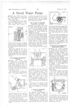
PATENT No. 733,579 comes from I Thompson Products Inc., Cleveland, Ohio. The subject is a pump for water or other liquid.
The drawing shows a section of the unit; the pumping member is a rubber " gear " (1), which rotates in a noncircular casing. When turning in a clockwise direction, spaces (2) adjacent to the inlet are continually expanding whilst those near the discharge port (3)are contracting; this creates the pumping action.
The pump discharges first into a turbulence chamber (4), from which the fluid overflows into a quiescent tank (5). The rubber rotor is sealed by a cartridge-brass disc at one end and a similar washer at the other, loaded by a spring.
• A TWO-STROKE COMBUSTION SYSTEM
PATENT No. 733,993 shows improvements in the combustion arrangements of spark-ignition twostroke engines, the aim of which is to enable a high compression ratio to be used and yet eliminate the tendency to four-stroke at low speeds. The patentee is Moteurs Goiot, 28 rue. du RCMLouis, Nantes, France.
The drawing shows a section of a cylinder head with the added modifica tion. An auxiliary chamber (1) is normally isolated from the combustion space by a closed valve (2). The latter can, however, be opened by a rocker (3) by manual means, by a governor or by a suction-operated device.
Under full load conditions the valve is .kept closed, but it is .opened at slow speeds or during idling. The effect is B30
to reduce the compression at a time when full efficiency is not necessary. The patent states that the scheme enables an engine to run with a flywheel much smaller than normal.
THE LATEST IN ELECTROMAGNETIC CLUTCHES PATENT NO. 734,049, comes from Eaton Manufacturing Co., Cleveland, Ohio, U.S.A., and shows a design for an electro-magnetically operated clutch. The drive is transmitted by .a combination of friction facings and solidified iron powder.
Referring to the drawing, the driven member is of the usual form, comprising a disc fitted with friction facings (1). These are loaded with iron powder so as to be semi-magnetic in nature and have only a low co-efficient of friction. Further outwards, at point 2, the disc is bare and is cut into numerous tangential slots. The space round the disc is partially filled with .a mixture of iron powder and graphite.
When the magnet (3) is not energized,
the tangential slots scoop the iron powder towards the centre against the action of centrifugal force. When current is applied to the windings, two things happen: the plates are magnetically united, bringing the friction facings into action, and the iron powder is attracted to space 4 where it is magnetically coagulated into a driving viscosity. The combination of the two actions effectively transmits the drive.
The patent states that by careful current control it is possible for the device to be used as an overload clutch which will disengage at a constant torque.
A SINGLE-CYLINDERED OIL ENGINE
A SINGLE CYLINDERED airt1 cooled oil engine is shown in patent No. 732,856, by A. Freeman Sanders, Redinnick House, Penzance, Cornwall. The chief feature is the arrangement of the cylinder head so as to permit the use of very large valves.
The drawing shows a section of the head across the two valves. It will be
seen that the combined diameters of the valves exceed that of the cylinder liner, and to accommodate them, a pair of notches (1) is milled out of the liner. This feature also prevents a broken valve from falling into the cylinder bore.
The piston rings are positioned so that they do not reach the notches; this brings them a little lower than normal. A spherical combustion chamber is used, with the injector lying horizontally in it, and a passage at the bottom leads to the cylinder bore. This assembly lies at right-angles to a line joining the two valves.
COMBUSTION CHAMBER FOR HIGH-SPEED DIESELS
PATENT No. 732,938 (Hercules Motors Corp., 101 11th Street, SE.. Canton, Ohio, U.S.A.), shows a form of combustion chamber suitable for a high-speed four-stroke oil engine. The object of the design is to prevent distortion of the cylinder bore by the heat expansion of the chamber.
The drawing shows a section of the proposed combustion chamber. It is substantially spherical in outline, and passage I to the cylinder is tangential to the sphere. In a view looking along the passage, it would appear as a segment of an annulus.
Lip 2 is a feature of the scheme; its purpose is to intercept the line of spray and prevent fuel from reaching the passage direct.
The chamber is made in two parts (3 and 4), the material being heatresisting steel. They may be welded together. A slight cylindrical portion on the outside forms a small clearance (5), which allows for heat expansion of the lip portion, and so prevents the cylinder bore from being loaded out of round. Elsewhere from this point, heat transfer to the cooled block is encouraged by tight fits.