


Replaceable Platforms for Buses
Page 58
If you've noticed an error in this article please click here to report it so we can fix it.
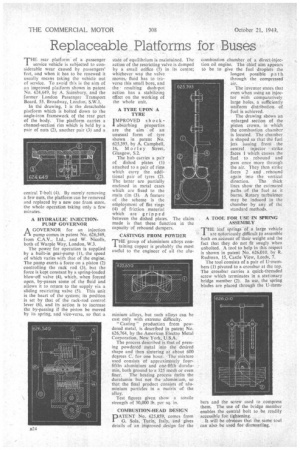
THE rear platform of a .passenger service vehicle is subjected to considerable wear caused by passengers' feet, and when it has to be renewed it usually means taking the vehicle out of service. To avoid this is the aim of an improved platform shown in patent No. 624,649, by A. Sainsbury, and the former • London Passenger Transport Board, 55, Broadway, London; S.W.I.
In the drawing, 1 lathe detachable platform which is bolted down to the angle-iron framework of the rear part of the body. The platform carries a channel-section rim which is held by a pair of nuts (2), another pair (3) and a central T-bolt (4). By merely removing a few nuts, the platform can be removed and replaced by a new one from store, the whole operation taking only a few minutes.
A HYDRAULIC INJECTIONPUMP GOVERNOR A GOVERNOR for an injection 1-1 pump comes in patent No. 626,549, from C.A.V.. Ltd., and W. Nicolls, both of Warple Way, London, W.3.
The power for• operation is supplied by a built-in gear-pump (1),. the speed of which varies with that of the engine. The pump exerts a force on a piston (2) controlling the rack rod (3), but the forte is kept constant by a spring-loaded blow-off valve (4), which, when forced open, by-passes some of the fluid and allows it to return to the supply via a sliding restricting valve (5). This, unit is the heart of the system; its position is set by that of the rack-rod control lever (6), and its action is to increase the by-passing if the piston be moved by its spring, and vice-versa, so that a
state of equilibrium is maintained. The action of the restricting valve is damped by a small orifice (7) in its centre; whichever way the valve moves,fluid has to traverse this small bore, and the • resulting dash-pot action has a stabilizing effect on the working of the whole unit.
A TYRE UPON A TYRE
IWIPROVED sh ock abSorbing properties are the aim of an unusual form of tyre shown in patent No. 625,393, by A. Campbell, 16, Morley Street, Glasgow, 5.2.
The hub carries a pair of dished plates (1) attached to a pair of rims which carry the additional pair of tyres (2). The latter are partially enclosed in metal cases which are fixed to the main rim (3). A feature of the scheme is the employment of flat rings (4) of friction material which are gripped between the dished plates. The claim made is that these function in the capacity of rebound dampers.
CASTINGS FROM POWDER
THE group of aluminium alloys containing copper is probably the most useful to the engineer of all the alu
minium alloys, but 5uch alloys can he cast only with extreme difficulty.
"Casting" production frOm powdered metal, is described in patent No. 626,764, by the American Electra Metal Corporation, New York, U.S.A.
The process described is that of pressing powdered metal into the desired shape and then sintering at about 600 degrees C. for one hour. 'The mixture used consists of approximately. fourfifths aluminium and one-fifth doraliimin, both ground to a 325 mesh or even
finer. The heating process Melts the duralumin but not the aluminium, so that the final product consists of aluminium particles in a matrix of the
Test figures given show a tensile strength of 30,000 lb. per sq.-in.
COMBUSTION-HEAD -DESIGN
DATE,NT No. 625,859, comes from 0, Sala, Turin; Italy, and gives details of an improved design for the combustion chamber .of a direct-injection oil engine. The chief aim appears to be to give the fuel droplets the longest possible path through the compressed
air.
• The inventor states that even when using an injector with comparatively large holes, a sufficiently uniform distribution of fuel is achieved.
The drawing shows an enlarged section of the piston crown, in which the combustion chamber is located. The chamber is shaped.so that the fuel jets issuing froni . the central injector strike facts I which causes the fuel' to rebound and pass once more through the air. They then strike . faces 2 and . rebound again into the vertical direction. The thick lines show the estimated paths of the fuel as it burns. Rotary turbulence may be induced in the chamber by any of • the standard methods.
, A TOOL FOR USE IN SPRING ASSEMBLY THE leaf 'springs of a large vehicle • are notariously difficult to assemble both on account of their weight and the fact that they do not fit snugly when unbolted. A tool to help in this respect is shown in patent No. 626,010, by R. Rudman, 15, Castle View, Leeds, 7.
The tool consists of a pair of U-memhers (1) pivoted to a crossbar at the top. The crossbar carries a quick-threaded screw which terminates in a stationary bridge member (2). In use, the spring blades are placed through the U-reem
bets and the screw used to compress them. The use of the bridge member enables the eentral bolt to be readily accessible for. tightening.
It will be obvious that the sank tool can also be used for dismantling.