


A Magnetic Gearbox for Track-layers
Page 34
If you've noticed an error in this article please click here to report it so we can fix it.
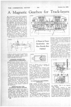
AN adaptation of the Cotal magnetic gearbox to endless-track vehicles is shown in patent No. 511,791, by J. Cotal, 2, rue de Saint-Marceaux, Paris. The power shaft (2) carries a bevel gear engaging with two free bevels on the shaft (1). By means of a sliding dog, either of these two bevels can be clutched to the shaft (1), thus giving a choice of direction.
The individual shafts (3) for the wheel drives are actuated via the wellknown Cotal magnetic gear, in which epicyclic elements are held or released by magnetic clutches. A further epicyclic reduction gear is shown, generally, at 5; this gives a low gear for emergency use and is brought in or out of action by a sliding bolt (4).
The steering of the vehicle is con trolled by electric contacts operated by turning the steering wheel ; these energize the appropriate magnets and so cause a slowing of one track.
STEERING SYSTEM FOR INDEPENDENT SUSPENSION.
FROM Morris Motors, Ltd., and A. Oak, both of Cowley, Oxford, comes pateat No. 511,766, describing a form of steering mechanism intended for use with independently: sprung wheels. The drawing shows a plan of the front of the vehicle, in which the independent suspension linkages (4) are attached to a cross-member indicated by the loop (3). Attached to the cross-member is a guide (I) for a sliding track-bar. This is extended via universal joints (5) to the rods (2) operating the stub axles.
The steering gearbox is of conventional type. and can be linked to either the steering arm (as shown) or to the sliding track-bar. The fact that the joints (5) are in the same plane as the axes of the links (4) means that the parallelism of the wheels is unaffected by road shocks.
IMPROVED SEAL FOR HYDRAULIC BRAKE PISTONS.
1"11E usual hydraulic brake piston is sealed by a rubber cup-washer, a method which, although effective, has the objection that there is a loss of energy owing to the high friction between rubber and metal. To avoid this is the object of an improved seal shown in patent No. 511,546 by J. , A32 Pratt, G. Manley and A. Girling, all of Guildhall Buildings, Navigation Street, Birmingham.
The proposed scheme employs a split ring (I), rather like a piston-ring, which is pressed on to a highly finished face on the piston by a spring-loaded washer, The initial good working fit of the ring is maintained by outward pressure caused by the working fluid. Other modifications are also shown, one of which uses a conical spring-loaded washer to assist the expansion of the split ring, TO DISENGAGE REAR-WHEEL STEERING.
N vehicles provided with means Li for steering through all wheels, it is desirable, in certain circumstances, to disconnect the rear-wheel mechanism and lock it so that the rear wheels are
held straight. A device for accomplishing this is described in patent No. 511,120, by Daimler-Benz A.G., Stuttgart, Germany.
Within an oil-tight steering box are two meshing gear segments (3 and 4). On the shaft, to which segment 3 is fixed, is a drop-arm (2) coupled by linkage to the front-wheel steering and therefore, permanently operated by tilt steering wheel_ A second drop-arm (1 is linked to the rear-wheel steering. 03 its shaft segment 4 is free to slide bu not to rotate.
Forming a unit with 4 is a slottet collar (5) and corresponding with i are dogs (6) fixed to the. housing. Pro vision is made for displacing segment axially, so that it may be moved on of mesh with segment 3, whereupa collar 5 immediately meshes with dog 6, and arm 1 is held immovable.
Attached to segment 3 is a speciall shaped plate (7) which renders i impossible for segment 4 to be shifte along its splines until drop-arm 1 is i the position at which the rear whee: are straight. This is safety feature. an imports The sliding segment is shift tluough a device incorporating te scopic elements, having a spring int posed between them. Thus, if t control lever be operated when the rt wheels are not straight, the spring be compressed, loading the mechani so that the segment is automatica shifted when it is in the right place.