


Methods of Mounting the Engine at the Side
Page 43
If you've noticed an error in this article please click here to report it so we can fix it.
SOME interesting details and illustrarions of the side-engine motorbus put into service recently by the London General Omnibus Co., Ltd., have already been placed before our 'readers in the issue of this paper dated September 9. Further explanation is revealed by the Patent specification now published in the names of Messrs: G. J. Rackharn, A. J. Stubbings, and the Associated Equipment Co., Ltd., Southall. Patents Nos. 380,537 and 380,670 relate to various arrangements of the units, with the object, mainly, of providing more room for passengers, as by this arrangement the space usually occupied by the engine and auxiliaries can be made available for seats.
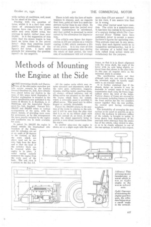
In patent No. 380,537 the engine is placed outside the longitudinal side members of the frame, and the cylinders are set at an angle of 20 degrees to the vertical, so that the seats which are above need not be unduly high from the floor and so that the head of the cylinder block can be removed while the engine is in place. A metal casing entirely separates the engine from the main part of the body. The end view is a section on the line 3.3.
All the engine units which may require attention and adjustment, such as the valve gear, carburetter, magneto, dynamo, starting motor, sparking plugs, oil cleaner, oil-level indicator, and oil filling orifice are situated on the side of the engine which faces the outside, where a removable panel is provided to afford access. This panel may be either hinged or entirely detachable.
Patent No. 380,670 relates to the position of the worm in relation to the axle, and it will be seen from the plan view that it is set at an oblique angle with the axle instead of, as usual, at rightangles, the object apparently being to provide a more direct transmission from the engine.
In another plan-view the engine is shown set at a slight angle with the side frame, so that it is in direct alignment with the worm shaft, the angle of the Latter with its axle being slightly reduced from that shown in the plan-view. rn this case all angular drive on the universal joints is avoided.
The specification points out that although only one rear axle is shown, the invention might be equally applicable to six-wheeled vehicles.
It is further explained that if the chassis design so permits it may be desirable in certain eases to have the transmission shaft cross the frame longitudinal above the level of the latter. Various shapes of frame are covered by the inventors, including frames in which the front portion has the two members nearer together than the rear portion, the central part having converging members.
The desirability of arranging the rear springs as far apart as possible, so as to reduce the tendency to sideways rolling of the vehicle, is brought to notice, it being shown how displacement, of the rear-axle drive sideways from the centre line of the vehicle, when viewed in plan, so as to be closely adjacent to one of the rear springs, is useful in this respect.