


SOME WORKSHOP TIPS.
Page 29
If you've noticed an error in this article please click here to report it so we can fix it.
Useful Hints *Which Should Interest Motor Vehicle Mechanics.
TWO interesting and useful tools are described and illustrated in a contribution which we have received from " G.H.L.", who lives in far-off Washingtoe, U.S.A. One of the.sketches shows a bearing block or support for a scraper intended as an aid to scraping the surfaces of main and big-end bearings. The other shows, in detail and in general arrangement, a guide for a hack-saw.
The block-bolder consists of a piece of metal shaped as shown in one of the sketches which explains both the form and the use of the block.
The base of the block is rounded so that it will rock upon the inner surface of the bearing which is being scraped. The bevelled upper surface shown is so made in order to afford different positions for the scraper. The other tool described by this correspondent is more ambitious in its aims, and certainly much more complicated. It provides a guide for a hack-saw, as well as a mechanical feed for the tool, and a stop to prevent cutting too deeply.
In this case, as in the previous one, the drawing is so clear as to render a-ny elalanrate description unnecessary. The hack-saw frame is T-shaped in section for the major part of its length. At one end it is prepared for a handle, and embodies a fixed lug for the reception of One end of the blade. At the other end it is drilled to accommodate a bellcrank lever,, onearm of which receives the other end of the hack-saw blade ; the other arm is drilled and tapped for a 'set-screw, the end of which makes contact with the back of the frame.
• A metal bracket is slotted • to correspond with the 'T-shaped part of the saw frame, which slides -within it. This bracket iswelded or brazed ,to two upright tubes, and to the tubes again, above the bracket, is a cross-niece designed to accommodate a threaded bush into which the feed-screw fits.
Two vertical, guides, on which the aforementioned tubes slide, are bolted to the table of the machine, and at the top of the guides, joining them, is an: other cross-bar, against which the feedscrew handle bears. The tubes, and the bracket in which the saw frame slides,' are lowered, as the saw cuts into the work, by manipulation of the feed-screw. A split sleeve on one of the guides, cap. able of being placed in any required position and secured by beim, tightened on the guide by means of a set-screw, serves as a stop to limit the depth of cut.
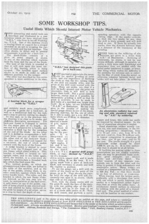
MOST mechanics appreciate the necessity for careful grinding of twist drills, and the' importance of finishing the work so that the two cutting edges of the drill are exactly alike, and the point of the drill truly central with the body. Many are aware, too„,tha,t if a drill be badly ground, and the point net -concentric, then it will drill a hole larger than itself. Not a great number, however, realize that it is possible, by deliberately grinding a drill so that its point is eccentric, it can be made to drill holes of a specified size, larger than itself. So at least, we are infornied by " H.A.B." of Rotherham. He.has even gone to the trouble of making the special gauge shown in one of the accompanying sketches, by the use of which he is able to make, say a On, drill bore holes which are 17-32-in: in diameter, The gauge in question is made of *-in. square steel bar, a piece about DI ins, long sufficing for the purpose. It is sharp ened at one end, and bent twice at right angles, 2 ins. and 4. ans. from that end, as the sketch shows. The A special drill gauge block, or regisdevised by
ter (C), is made of s-in. or Fin. square stuff, and is made a nice sliding fit on the stem. E is a, spring made from a piece of. hack-saw blade, and necessary to steady and hold the register in position. To use the gauge, set a drill with its centre of the shank on the point of the gauge, as at, D. Then elevate the register until the edge of the drill will conveniently rest upon it, as shown. Chalk that side of the register.
Now, with the shank centre still on the point D, mark the face of the register with ono cutting edge of the drill. The mark will be in the form of an arc of a circle with centre at D. Tura the drill round, and perform a corre
sponding operation with the opposite cutting edge. If the marks coincide, so that the two marks be one, then the drill is truly ground, and will drill dead to size. If there be actually two marks, then the distance between them is a measure of the inaccuracy af thegrinding.
Q OME hints on the soldering of ahrAlminiimi are given in a letter from "AK" of Manchester. Soldering of aluminium he states, is not. by any
ff
means difficult, although it certainly requites a little more care, knowledge and experience than are needed when the metal under treatment is coppe or brass. One thing which makes for difficulty is the necessity for extreme care in removing the film, of oxide from the metal„ as otherwise cohesion between metal and "solder will not take place. In soldering
copper and brass, this oxide can easily be removed by chemical means. In the vase of aluminium abrasion is needed.
Good aluminium solders usually contain tin, zinc and aluminium, in the following proportions :—Aluminium, from 5 to 15 per cent. ; zinc, from 10 to 25 per cent. ;and tin, from 70 to 85 per cent. A typical composition is aluminium 10 • per cent., zinc 15 per cent., and tin 75 per cent. The tensile strength of a good aluminium solder should he about 7,000 lb. per sq. in. It is very undesirable that it should be at all brittle.
If facilities for making solder to these prescriptions are not readily 'available, then one may be purchased ready made. Two good examples are Af umin Solder and All-Unite Metal. The Tatter consists of two separate compounds, one to form the joint and the other to protect it from atmospheric and electrolytic. action. These selders are worked at a temperature of from 510 deg. to 600 deg. Fah., so that there should be no fear of distortion or weakening.
When tinning, heat the broken parts, preferably with a blowlamp (but never With one which is partly luminous and smoky) to a temperature rather higher than that at, which the solder fuses. A satisfactory tinned surface is obtained by-rubbing with the point or a tinnedsteel tool. The actual method of soldering will be familiar to our readers.