


TRANSMISSION BY ELECTRICAL MEANS.
Page 15
Page 16
If you've noticed an error in this article please click here to report it so we can fix it.
3.—The Principle of Various Practical Systems.
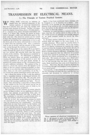
WE WILL NOW endeavour to indicate in simple form the essential character of the various systems of electrical transmission that have actually been put upon the market with at least some measure of success. In Fig. 1, E represents the engine viewed from above ; C is the clutch; D is a dynamo from which electrical connections are taken to a motor (M), whence the power is transmitted through a shaft and diffefential gear to the back axle (A). The electrical system can be varied to meet the varying requirements of ordinary running conditions by altering the connections, so as to put the field coils of the motor alternatively in series and in shunt with the armature coils. Also a resistance may be put in circuit, and the amount of this resistance varied through the medium of a controller.
In Fig. 2 the power of the engine (E) is, as before, taken through the clutch (C) to a dynamo (D). There are two motors (M) actually built into the power wheels of the vehicles. The dynamo is connected to both of these motors. No differential is required. With two motors there are greater possibilities of varying the connections of the system to meet the varying conditions of road and speed, though in practice the system shown in Fig. 1 is found to admit of quite sufficient variations. The system in Fig. 2, however, allows the current from the dynamo to be taken to the two motors running in parallel, or alternatively, to one after the other connected up in series. Also, there are the same possibilities as in Fig. 1 of varying the actual connections inside each motor.
Fig. 3 shows the system of Fig. .1 with the addition that a secondary battery is interposed between the dynamo (D) and' the motor (M). We can now store the current generated in the dynamo in the battery (B) when the running conditions are light. For example, when descending a steep hill or when pulling up the vehicle on the level, the motor can be run as a dynamo to generate current, none of which is, for the time being, used for propulsion.
The generation of th's current., of course, absorbs power, so -that, in effect, we are applying an electrical brake, but instead of generating heat only we generate mainly electricity and only a little heat. The electricity we can turn to good account later on when the running condifons are less favourable.
Thislis, in fact, the regenerative system to which we referred in our last article. We can, of course, vary the connections very considerably. As already explained, we may feed current to the battery and disconnect the motor altogether. On the other hand, we may let the current run past the battery to the motor without the battery being connected up at all. If preferred, we can keep the battery in the circuit and use it as a reservoir, which is both receiving and supplying current at the same time. For starting purposes we can get the car moving by supplying current from the battery to the motor. If we were then to provide a shaft with a clutch between the dynamo and the motor, we could let this clutch in when the car was moving sufficiently rapidly, and thus start the engine Again, it has been mentioned that a dynamo can be designed so as to function as a motor. Consequently, if we provide for the connections of the dynamo to be varied at will, we could supply current from the battery to the dynamo and run the dynamo as a motor to start the engine.
Evidently, we could introduce a battery in just the same way into the system shown in Fig. 2, but, as this would involve no principle not already referred to, no good purpose would be served by illustrating it.
In all these systems referred to above the transmission from the engine to the road wheels is invariably electrical. There must be electric losses in the dynamo, in the connections, and in the motor, and if we employ resistances to regulate the supply of current from the dynamo to the motor, we are, in effect, converting electric'ty into heat and so sacrificing a certain amount of efficiency. Altogether, then, it must be apparent that the efficiency of a purely electric drive cannot be anything like so good as the efficiency of a direct mechanical drive from engine to back axle. We cannot, of course, use a direct drive in all circumstances with the ordinary type of vehicle, but we can provide that the drive shall be direct under those conditions that occur most frequently in practice. Moreover, the loss of power involved by transmitting through well-designed trains of gears is by no means great.
Consequently, in this respect the mechanical system has the advantage all down the line, and this fact has naturally led inventors to endeavour to arrange matters so that, under fairly easy running conditions, the drive could be mechanical without prejudice to the fact that under stiffer conditions the drive shall remain at least partly electrical.
Suppose that we were to provide an ordinary mechanical transmission system but mount upon our transmission shaft a dynamo and a motor or a machine which could perform either function. If, in addition, we were to carry a battery, we could, when descending hills or stopping, connect up in order that the dynamo would charge the battery. Under conditions of heavy work, we could take current from the battery to drive the motor, and this would assist the engine so that we might be able to do without the ordinary change-speed gears.
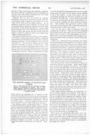
The system would, however, involve a very substantial battery, and probably there would be insufficient opportunities of charging this battery under ordinary running conditions ; also, the efficiency of a battery is decidedly low. The result of taking out more than was put in would, of course, be disastrous. The battery would become discharged and would be unable to help, and we should find ourselves with a car having only one fairly high speed and quite incapable of tackling a steep hill. Thus, we must look for some better system of combining the lvantages of the mechanical and the electrical systems of transmission. One such system that has been notably successful is the Thomas electro-mechanical transmission. This is of British origin. Another practical design is the Owen magnetic system, which hails from America.
The Thomas system is indicated in Fig. 4. It will be observed that the position usually occupied by the clutch is taken by a double system of epicyclic gears. The sun wheel of the first system is keyed to a shaft which runs straight through to the .back axle and carries the electrical machine (M). The sun wheel of the second system is fixed to a sleeve carrying the electrical machine (D). Between the two electrical machines is a clutch, so arranged that when it is engaged the sleeve and the shaft run solid. The two electrical machines are both, in fact, capable of functioning either as dynamos or as motors. Now, B36 when the clutch (C) is disengaged there are two roads along which the power of the engine can be applied to drive the vehicle. A part of the power can be transmitted through the forward epicyclic gear and the shaft to the back axle. A part can be transmitted through the second epicyclic gear to the dynamo or, more correctly speaking, the first electrical machine (D). This machine then generates current which drives the second machine (M), which thus assists by electrical means to drive the vehicle.
Now we can get a direct mechanical drive by engaging the clutch (C). Whe,n this clutch is engaged the epicyclic gear runs solid, and the electrical machines take no part in the transmission of power. This, then, is the state of affairs when running conditions are fairly easy, all electrical losses being then eliminated.
Under more arduous runningconditions, the clutch (C) is disengaged and the epicyclic gear acts as a sort of balance, so that part of the power is always transmitted mechanically, but a varying percentage of it is transmitted electrically. It does not appear possible, without going into very full details and showing exact diagrams of the system, to explain it more clearly than this. It is hoped, however, that this brief description will suffice to show that it attains the object of eliminating electrical losses to the fullest possible extent. This it does at the expense of introducing, under some running conditions, the additional losses involved in the use of an epicyclic gear.
The Owen system, which is indicated in Fig. 5, is materially different in principle. Here, again, there are two electrical machines (D and M). In all the other systems described the electrical machines have been so arranged that their armatures rotated, but their field magnets were fixed stationary to the frame of the vehicle. In the Owen system the field magnets of the dynamo (D) form a part of what may 15e described as a magnetic clutch. These field magnets are rotated by the engine. The result is the generation of a current in the armature, which is mounted on the shaft running to the back axle. This current is led to the motor (M), Which then gives power and causes the shaft to rotate. The faster the shaft rotates the less is the relative motion between the field magnets and armature at D, and the less therefore is the current generated.
Under light running conditions, the consequence is that the field magnets and armature of D runs at almost the same speed as one another. The effect is that of a clutch which is slipping only slightly. Under heavier conditions the slip is greater, and the electric machines take a much bigger share in the work. Evidently, there must always be some loss, which may be described alternatively as an electrical loss or as that due to the slipping of a. clutch, but something very nearly approaching a direct drive on top speed is obtained. It would, of course, be possible in principle to arrange for the whole machine D to be locked, so as to run solid with no electrical loss.
These notes are admittedly incomplete, but it is hoped that they will at least serve to enable the reader to classify and to understand the principles of any system of transmission, involving electricity, which he may see described in detail or embodied in the design of a vehicle.