


ROAD AND WORKSHOP by HANDYMAN
Page 54
If you've noticed an error in this article please click here to report it so we can fix it.
Safe Slinging
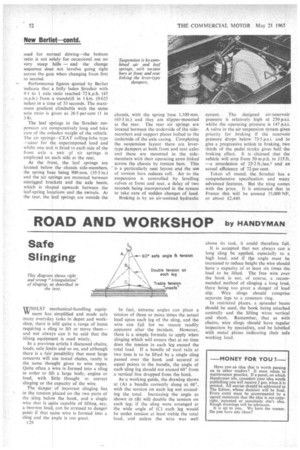
This diagram shows right and wrong "triangulation' of slinging, as described in the text.
MHILST mechanical-handling equipYV ment has simplified and made safe many everyday tasks in depot and workshop, there is still quite a range of items requiring a sling to lift or move them— and not always can it be said that the lifting equipment is used wisely.
In a previous article I discussed chains, loads, safe limits and so on, and although there is a fair possibility that most large concerns will use tested chains, rarely is the same thought given to wire ropes. Quite often a wire is formed into a sling in order to lift a large body, engine or load, with little thought to correct slinging or the capacity of the wire.
The danger of incorrect slinging lies in the tension placed on the two parts of the sling below the hook, and a single wire that is quite capable of lifting, say, a two-ton load, can be stressed to danger point if that same wire is formed into a sling and the angle is too great.
c26 In fact, extreme angles can place a tension of three or more times the actual load upon each leg of the sling, and the wire can fail for no reason readily apparent after the incident. However, there is a simple formula to apply when slinging which will ensure that at no time does the tension in each leg exceed the total load. If a bundle of steel rails at two tons is to be lifted by a single sling passed over the hook and secured at equal points in the bundle, the angle of each sling leg should not exceed 60° from a vertical line dropped from the hook.
As a working guide, the drawing shows at (A) a bundle correctly slung at 60°, with the tension on each leg not exceeding the total. Increasing the angle as shown in (B) will double the tension on each leg; if the sling were arranged at the wide angle of (C) each leg would be under tension at least treble the total load, and unless the wire was well
above its task, it could therefore fail.
It is accepted that not always can a long sling he applied, especially to a high load, and if tlae angle must be increased to reduce height the wire should have a capacity of at least six times the load to be lifted. The free wire over the hook is not, of course, a recommended method of slinging a long load, there being too great a danger of load slip. Wire slings should comprise separate legs to a common ring.
In restricted places, a . spreader beam should be used, the hook being attached centrally and the lifting wires vertical and short. Remember, that as with chains, wire slings should have regular inspection by specialists, and be labelled with metal plates indicating their safe working load.
—MONEY FOR YOU ?—
Have you an idea that is worth passing on to other readers? It must relate to maintenance practice. If a panel, on which Handyman sits, considers your idea worth publishing you will receive 3 gris, when it is printed. All entries should be addressed to The Editor, whose decision will be final. Every entry must be accompanied by a signed statement that the idea is not copyright, 'patented or somebody else's idea. Rough drawings will he adequate. It is up to you. We have tile money. Do you have any ideas?