


Fitting Four Driven Wheels to a Normal Vehicle
Page 72
If you've noticed an error in this article please click here to report it so we can fix it.
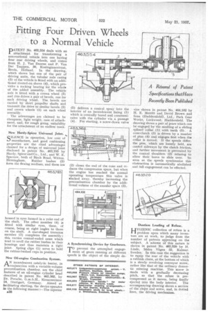
PNo. 463,554 deals with an attachment for transforming a conventional vehicle into one having four rear driving wheels, and comes from H. J. Van Doorne and P. Van Der Trappen, 30, Koninginnestraat, Breda, Holland. In the drawing, which shows but one of the pair of driving units, the tubular axle casing (3) of the vehicle is frtted with an additional riveted-on sleeve (4), which provides a rocking bearing for the whole of the added assembly. The vehicle axle is fitted with a crown wheel (5) and this drives a pair of bevels, one for each driving wheel. The bevels are carried by short, propeller shafts and transmit the drive to similar bevels (2) and crown • wheels (1) on each wheel
assembly.
The advantages are claimed to be cheapness, light weight, ease of attachment, and, for rough going, suitability for the attachment of an endless track.
New Hardy-Spicer Universal Joint.
SILENCEin operation, low cost of manufacture, and good cushioning properties are the chief advantages claimed for a design of universal joint disclosed in patentNo. .463,785 by Hardy, Spicer and Co., Ltd., and W. E. Sparrow, both of Birch Road, Witton, Birmingham. Rubber bushes (2) form the flexing medium, and these Ara
housed in eyes formed in a yoke end of the shaft. The other member (4) is fitted with similar eyes, these, of course, being at right angles to those on the shaft. A star-shaped trunnion member (3) completes the assembly ; this carries conical-ended arms which tend to swell the rubber bushes in their housings and thus maintain a tight joint. Spring clips (1) serve to hold the rubber-hushed cups in position.
New Oil-engine Combustion System.
A N incandescent catalytic heater, in conjunction with a variable-volume precombustion chamber, are the chief features of an oil-engine cylinder head described in patent No. 463,362, by Dr. Porsche, G.m.b.H., Kronenstrasse 24, Stuttgart, Germany. Aimed at facilitating starting, the device operates in the following manner :—The injector A38
(5 delivers a conical spray into the interior of an incandescent lining (I) which is conically bored and communicates with the cylinder via a passage (4). For starting, a screw-down valve
(2) closes the end of the cone and reduces the compression space, but when the engine has reached the normal operating temperature this valve is slacked away, thereby increasing the precombustion chamber by the additional volume of the annular space (3) .
A Synchronizing Device for Gearboxes.
prevent the attempted engagement of gears running at different speeds is the object of the simple de
vice shown in patent No. 464,102 by H. E. Merritt and David Brown and Sons (Huddersfield), Ltd., Park Gear Works, Lockwood, Htiddersfield. The drawing shows a pair of gears which can be engaged by the meshing of a sliding splined collar (1) with teeth (5). A cone-clutch (3) is driven by a number of pins (4) and engages first when the collar is moved. If the speeds differ; the pins, which are loosely held, are canted sideways by the clutch friction, and further movement is prevented by the conical shoulders (2) refusing to allow their bores to slide over. So soon as the speeds synchronize this obstruction is automatically abolished and full engagement can be effected.
Dustless Loading of Refuse.
H1YGIENIG collection of refuse is a problem upon which many inventors are at work, to judge from the number of patents appearing on the subject. A scheme of this nature is shown in patent No. 463,520 by H. Linde, Sbdra Vagen 32, Kalmar. Sweden. In this case the suggestion is to equip the rear of the vehicle with a rubbish chute, at the bottom of which is a slowly revolving conveyor screw, rather like that of the ordinary domestic mincing machine. This screw is made with a gradually decreasing pitch, so that the refuse is precompressed as it moves, being finally
ejected into the body interior. The accompanying drawing shows a section of the chute and screw, and, in dotted lines, the drivingmechanism.