


An Improved Mounting for Bus Bodies
Page 54
If you've noticed an error in this article please click here to report it so we can fix it.
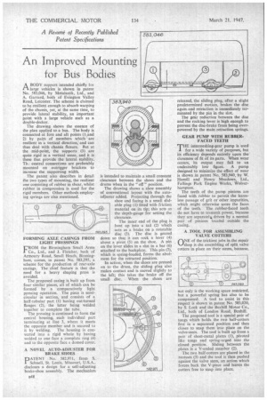
ABODY support intended chiefly for large vehicles is shown in patent No, 583,046, by Metalastik, Ltd., and A. Garrard, both of Evington Valley Road, Leicester. The scheme is claimed to be resilient enough to absorb warping of the chassis, yet, at the same time, to provide lateral stability, an important point with a large vehicle such as a double-decker.
The drawing shows the essence of the plan applied to a bus. The body is connected at fore and aft points (1 and 2) by pairs of members which are resilient in .a vertical direction, and can thus deal with chassis flexure. But at the mid-point, the supports (3) are quite rigid in a vertical sense, and it is these that provide the lateral stability. Th: central connections are preferably mounted on outrigger brackets to increase the supporting width.
The patent also describes in detail the two types of mounting, the resilient one consisting of rubber in shear, whilst rubber in compression is used for the rigid members. Other methods employing springs are also mentioned.
FORMING AXLE CASINGS FROM LIGHT• PRESSINGS
FROM the Birmingham Small Arms Co., Ltd., and J. Fletcher, both of Arrnoury Road, Small Heath, Birmingham, comes, in patent No. 583,295, a scheme for the production of rear-axle casings. The chief feature is that the need for a heavy shaping press is avoided.
The proposed casing is built up from four similar pieces, all of which can be formed by a comparatively light pressing operation. The piece is semicircular in section, and consists of a half-tubular part (1) having out-turned flanges (2), the latter being welded together to complete the tube.
The pressing is continued to form the central housing, each individual part terminating at line 3, where it meets the opposite member and is secured to
it by welding. The housing is converted into a rigid whole by having welded to one face a complete ring (4) and to the opposite face a domed cover.
A NOVEL AUTO-ADJUSTER FOR BRAKE SHOES
PATENT No. 582,971, from S. Schnell, St. Louis, Missouri, U.S.A., discloses a design for a self-adjusting brake-shoe assembly. The mechanism
is intended to maintain a small constant clearance between the shoes and the drums when in the " off " position.
The drawing shows a shoe assembly of conventional layout with the autoadjus er added. Projecting through the shoe and facing is a small slidable plug (1) fitted with friction material on its tip; this acts as the depth-gauge for setting the clearance.
The inner end of the plug is bent up into a tail (2) which acts as a brake on a rotatable disc (3). The disc is geared down so that it can rock a lever (4) about a pivot (5) on the shoe. A pin on the lever slides in a slot in a bar (6) attached to the backplate. This pin (7), which is spring-loaded, forms the abutment for the retracted position. In action, when the shoes are pressed on to the drum, the sliding plug also makes contact and is moved slightly to the left; this takes the brake off the small disc. When the shoes are released, the sliding plug, after a slight predetermined motion, brakes the disc again and retraction is immediately terminated by the pin in the slot.
The gear reduction between the disc and the rocking lever is high enough to prevent the disc-brake from being overpowered by the main retraction springs.
GEAR PUMP WITH RUBBERFACED TEETH THE intermeshing-gear pump is used for a wide variety of purposes, but its efficiency depends entirely upon the closeness of fit of its parts. When wear occurs, its output may fall to an undesirably low figure. A pump designed to minimize the effect of wear is shown in patent No. 583,940, by W. Hamill and Henry Meadows, Ltd., Fallings Park Engine Works, Wolverhampton.
The teeth of the pump pinions are faced with rubber to permit the harmless passage of grit or other impurities, which might otherwise score the faces of the teeth. The rubber-faced teeth do not have to transmit power, because they are separately, driven by a normal pair of pinions locafed outside the casing.
A TOOL FOR ASSEMBLING VALVE COI-II:RS ONE of the trickiest jobs in the repair shop is the assembling of split valve cotters in place on their stems, because, not only is the working space restricted, but a powerful spring has also to be compressed. A tool to assist in this respect is shown in patent No. 583,020, • by S. Lock and the Bexhill Motor Co., Ltd., both of London Road, Bexhill.
The proposed tool is a special pair of tongs which holds the two half-cotters first in a separated position and then closes to snap them into place on the valve-stem. The tool is built up from a pair of sheet-metal plates (1), pivoted like tongs and spring-urged into the closed position. Sliding between the plates is a V-ended member (2).
The two half-cotters are placed in the recesses (3) and the tool is then pushed against the valve stem, an action which forces back the V-piece and leaves the cotters free to snap into place.