


Patents Completed.
Page 20
If you've noticed an error in this article please click here to report it so we can fix it.
Complete specifications of the following patents will be sent to any address in the United Kingdom upon receipt of eightpence per copy at the Sale Branch, Patent Office, Holborn, W.C.
To Prevent Brakes Jambing.
J. Mackay.—No. 23,169, dated 20th October, 1911.—This specification describes a brake of the type in which an internal-expanding ring is operated by means of a cam which comes into contact with a brake drum. According to this invention, the ring is made thicker at the lower side so that it is more springy. A casing formed on the ring at this point engages a spring which is pressed against a pin carried by a fixed bracket. This spring tends to push the expanding shoe upwards and off the bearing surface. A tension spring is fixed between opposite sides of the expanding shoe near the free ends, and this tends to pull these together and therefore release the brake. The combined action of these two springs ensures the brake-shoe's being kept out of contact with the brake-drum as soon as the cam or equivalent element is moved into the off position.
Sparking Plug Improvement by Bosch.
Robert Bosch, Ltd.—No. 20,899/11. dated under International Convention 3rd December, 1910.—In order to ensure the satisfactory working of internalcombustion engines, high-tension sparking plugs must fulfil at least two conditions : (a) there must not be any deposit on the electrodes, and (b) the electrodes must be so constructed that they do not become incandescent when in use. Hitherto the residue deposited on the electrodes has been burnt off by allowing them to become incandescent, but this leads to faulty ignition and is therefore undesirable. According to the present invention, the electrodee are so formed that they become incandescent and cool so rapidly that before the next suction stroke they are no longer incandescent and faulty ignition cannot occur. The electrodes are made of a metal of a some what high melting point such as nickel, and several wires are brought down round the central insulated electrode. The ends of these wires are flattened out and brought into suitable proximity with the central electrode, so that the spark may pass between them. Owing to the very small mass and large superficial area of these flattened wires, they are raised to incandescence at the spark discharge, but cool down very rapidly immediately afterwards.
A Sleeve-valve Engine.
Arthur William Reeves.—No. 41, dated 1st January, 1912.—This valve gear is arranged with the object of providing (1) maximum valve area : (2) small lift : (3) a balanced exhaust valve : (4) a hemispherical combustion chamber : (5) central positioning of the sparking plug. The cylinder-head projects into the cylinder and is surrounded by a cylindrical sleeve-valve which has a seating upon the inner end of the head. An annular inlet-port is formed in the cylin der walls and communicates with the combustion chamber through a port in the vertical wall of the valve, and through the opening between the valve and its seating when it is displaced therefrom. Surrounding the inlet-valve is a cylindrical outlet-valve controlling annular ports for the exhaust. This outlet-valve is also provided with a port through which the inlet mixture passes. Suitable packing-rings are provided where required and the two sleeves are operated by any of the usual known forms of valve gear.
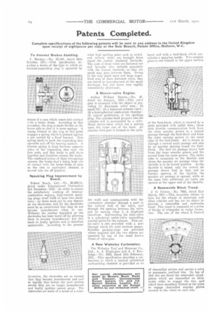
A New Wolseley Carburetter.
The Wolseley Tool and Motorcar Co., Ltd., A. A. Remington and A. J. Rowledge.—No. 3892, dated 16th February, 1911.—This specification describes a carburetter in which a vertical cylindrical carburetting chamber is provided at its
lower end with a feed-block which constitutes a spraying nozzle. Two annular grooves are formed in the upper surface of the feed-block, which is covered by a plate provided with radial slots; these slots provide communication both from the inner annular groove to a central passage through the feed-block and from the outer annular groove to the outer edge of the feed-block. Air is drawn in through a central axial passage and also by an annular opening round the feedblock. The first air passage draws fuel from the inner annular groove and the second from the outer groove. The choke tube is connected to the throttle and closes the annular air passage when the throttle is in its lowest position. As the throttle is raised, only the central air passage draws fuel at, first, and on further opening of the throttle the annular air passage is opened, while at the same time additional air inlets are opened at the upper end of the throttle.
A Renewable Block Tread.
J. 0. Cowrie.—No. 7005, dated 21st March, 191.1.—This invention relates to tires for the wheels of motorcars and other vehicles and has for its object to provide a removable and renewable tread. This tread is composed of a series of blocks of triangular or wedge fo-rmation. The rim of the wheel is formed
of channelled section and carries a solid or pneumatic resilient tire. On top of this tire are fitted the removable treadpieces which are channelled on their under sides to engage the tire, and which have shoulders formed at the sides to engage channelled annular plates secured to the wheel on each side.