


A Clever New Engine
Page 60
If you've noticed an error in this article please click here to report it so we can fix it.
WILST the internal-combustion engine has a higher thermal efficiency than any other type of primemover, there is still room for improvement, in view of the fact that the actual thermal results fall short of those possible by more than 50 per cent. In .patent No. 428,049 is described an ingenious engine in which, whilst the compression ratio may remain normal, the expansion ratio may be increased to any desired extent. The inventor is P. St. G. Kirke, M.A., .A.M.I,C.E., A.M.I.M.E., A.M.I.E.E., of Givons Manor, Leatherhead. The scheme employs an additional cylinder to each pair of normal fourstroke cylinders. In the drawing, the two outer cylinders (1 and 3) are conventional, and, although the pistons oscillate together, the cylinders fire alternately. The centre cylinder is provided with special valves (2) which connect it; in turn, to each of the outer cylinders for one complete revolution of tha crankshaft. The result is that the centre cylinder is operated on a twostroke cycle, sharing the explosion and exhaust strokes of each of the outer cylinders in turn, By this means, the inventor claims, any desired expansion ratio may be obtained, thus utilizing up to 90 per cent, of the possible temperature drop of the combustion products. A further advantage is that silencirg becomes no longer a problem, it being possible to reduca the exhaust pressure to that of the atmosphere, if desired.
A New Brake.operating Assembly.
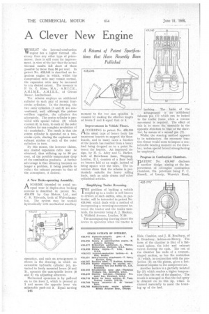
A SCHEME intended to avoid tin tl wear in duplex-shoe braking systemx is described in patent No. 428,075 by Guy Motors, Ltd., and C. K. Edwards, both of Wolverhampton. The system may be worked hydraulically with mechanical auxiliary operation, and such an arrangement is shown in the drawing, in which an extensible hydraulic cylinder (4), attached to freely mounted levers (6 and 7), operates the cam-spindle levers (8 and 5) via adjusting setscrews.
Mechanical operation is by pull-rod on to the lever 2, which is pivoted at I and moves the opposite lever via adjustable push-rod 3. Equal turning n46
moment to the two cam spindles is ensured by making the effective length of levers 2 and 8 equal that of 5.
Improvements in Vehicle Floors.
ACCORDING to patent No. 428,300 the usual type of heavy body has transverse bearers to support the floorboards, and in many cases a fracture of the boards has resulted from a heavy load being dropped on to a point lletween the bearers. An improved design, by H. C. Adey and G. Barker, both of Brewhouse Lane, Wapping, London, E.I, consists of a floor built on bearers laid at an angle, instead of being square with the sides. The inventors claim that the scheme is particularly suitable for heavy rolling loads, such as cable drums and other cylindrical articles.
Simplifying Trailer Reversing.
THE problem of backing a vehicle coupled tip to a trailer is well known to drivers of such outfits, who, in particular, will be interested in patent No. 428,046, which deals with a method of incorporating a reversing movement between the tractor and the trailer turntable, the inventor being A. J. Mackay, 2, Walfield Avenue, London, N.20. The accompanying drawing shows the device in operation when the tractor is backing. The • basis of the arrangement is an additional fulcrum pin (I) which can be locked to the trailer frame .. when a reverse . movement i5 required. The effect of this is to move the turntable in the opposite direction to that of the drawbar, by means of a second pin (2). Whilst the steering method appears to be satisfactory, the necessary tractive thrust would seem to impose a considerable bending moment on the drawbar, unless special lateral strengthening be employed.
Progress in Combustion Chambers.
DATENT No. 428,067 discloses I another design aiming at the improvement, of oil-engine combustion chambers, the patentees being F. C. Russell, of Lundy, Warwick Road, Hale, Cheshire, and J. H. Bradbury, of 8, Broadway, Ashton-on-Mersey. The form of the chamber is that of a flattened sphere, the inlet and exhaust valves forming the cnds. The rest of the chamber has walls of a crescentshaped section. as has the restriction (1) which, in conjunction with the projection (2) on the piston, gives a lastmoment impulse to the compressed air. Another feature is a partially isolated lip (3) which reaches a higher temperature than the rest of the chamber.The nozzle is arranged so that the fuel spray is directed on to this lip, which is claimed materially to assist the breaking up of the fuel.