


A Simple Hydraulic Pump for Tipping Vehicles
Page 50
If you've noticed an error in this article please click here to report it so we can fix it.
I".
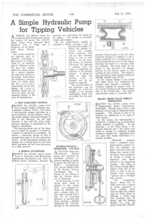
A SIMPLE and efficient pump for producing high fluid-pressure forms the subject of patent No. 637,679, Which comes from Edwards Bros. (Tippers), Ltd., , J. Edge and J. COsgrove, all of Brad
ford Street, Bolton, Lancs. , The pump comprises an , opposed pair of cylinders containing a dual piston (I) reciprocated by an eccentric pin (2). Delivery valves (3) pass the output, whilst the intake occurs via a central chamber (4) andports drilled in the piston. Each piston also contains a one-way valve (5) which closes on the outstroke. Lubrication can be forgotten, the central chamber being full of oil at all times. An outstanding feature is the ease of manufacture.
A NEW INJECTION SYSTEM
DATENT No. 637,702, comes from
the Cummins Engine Company Inc., Columbus, Indiana, U.S.A., and shows a fuel-injection system operating on a novel principle. In this scheme a metering puny supplies measured 'charges of fuel to the injectors, but the fuel pressure is low, and the actual highpressure injection is performed by the injectors themselves.
The drawing shows one of the injectors, in which the plunger is worked by a:rocker (I) operated by a camshaft. In action, a measured charge of fuel is pumped into space 2 via two non-return valves. At the appropriate moment, the plunger (3) is forced down by the camshaft, and ejects the fuel from the nozzle at a high pressure.
A SIMPLE GOVERNOR
DATENT No. 637,667, which comes from F. Entwistle, and Brockhouse Engineering (Southport), Ltd., both of Rufford Road, Southport, discloses erii,
governor for controlling the speed of an engine. The design is extremely simple and compact. On the engine-driven spindle is mounted a flange carrying a pair of pivoted bob-weights (I).
When the spindle revolves, the weights move outwards and rub on their housing, which is free to turn slightly. As the housing moves, an external cam-track (2) operates a rocking lever (3) which is connected by rodwork to the throttle
control. A spring (4) tends to open the throttle, a nd its strength can be adjusted as required.
The characteristics of the governor can be changed by adding weights to the existing bobweights, which may be drilled for this purpose.
HYDRAULICALLY OPERATED CLUTCH
A CLUTCH using con 1—kventional friction,' plates, but actuated by hydraulic pressure instead of springs, is shown in patent No. 617,236, by
Hobts Transmission, Ltd., and H. Hobbs, both of 78, Russell Terrace, Leamington Spa. ' A feature of the scheme is that the friction plates are oil immersed.
In the drawing, 1 is the driven plate which is splined to the output shaft. It is gripped between the flywheel face and a presser plate (2). The latter is faced with a disc (3) of insulating material, to prevent heat from reaching a flexible diaphragm (4). This diaphragm is the energizing
member, being forced to the left when hydraulic pressure is applied to it by a pump connected via a running joint. A cock (5)controls the action of the pump, diverting the liquid to a by-pass when not required. The main point of the patent is the provision of annular grooves in the presser plate so. that cooling oil can circulate. The clutch is also covered by other patents numbered 596,908, 628,499 and 637,251.
In the original design it was found that under severe test conditions the pressure plate showed a tendency to overheat, making for greater wear, of the friction facing on the pressure-plate side of the friction disc. The present improvement seeks to overcome this.
BRAKE SHOES HAVE DIRECT OPERATION
PATENT No. 637,811, comes -from Hoppenstand • Brake Corporation, Pittsburgh, Pennsylvania; US.A.-, and discloses a novel type of hydraulic brake expander. The scheme is said"to be suitable for application to all types of
road vehicle. . • In this system, the brake-facing.' is backed by a:resilient bag to which fluid under pressure is admitted. In the drawing I is. the brhke drum, 2 the friction material and 3 the rubber .bag which is housed, in a specially shaped stationary member (4). Segmental units are used, four being mentioned as a suitable number. .
. Hydraulic pressure
from a standard Lockheed system is used to inflate the chamber via pipe 5 and thus move the facing into contact with the drum. Each quadrant of facing is boxed in edgeways and firmly secured to its supporting member. The radius of the friction facings differs slightly from that of the drum, so that as the expansive force increases, a greater area is brought into contact.
"The Commercial Motor" dated July 19, 1946, dealt with a system of brake operation in which multiple shoes were brought into contact with the brake drum by inflating a rubber bag. The patentees were H. Butler and. the Dunlop Rubber Co., Ltd., the patent being No. 576,767.