


A Built-up Crankshaft 55!,567 • A Resume of Patent Spedfications
Page 36
If you've noticed an error in this article please click here to report it so we can fix it.
That Have Re, cently Been Published MANY advantages are claimed for a design of built-up crankshaft Shown in patent No. 561,567, by Century Motors Corporation, Dearborn,
Michigan, U.S".A. The chief feature is that each crankpin and each main journal can be separately detached to enable renewals to be made without dismantling the whole engine. Moreover, one-piece big-ends can be employed instead of the usual split' variety.
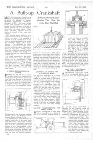
The drawing shows sufficient of a crankshaft to illustrate the methods of joining the parts. The crankpin is serrated, as at 1, and the faces of the webs are similarly shaped so as to lock the assembly rigidly when bolted together, The serrations are either straight or curved on a large radius: they are visible at point 1 because it shows an end view. Similar means unite the webs to the journals, but the serrations, in this case, being in a vertical direction, are represented only by lines (2).
To ensure concentricity, the uniting bolts may be made with a close-fitting portion (3), or, alternatively, a clear bolt may be used in conjunction with an aligning sleeve (9). The patentee• envisages the use of hard steel big-ends and main bearings, with • renewable crankpins and journals, possibly made from bronze.
A SIMPLE SELF-ENERGIZING CLUTCH
pATENT No. 561,335 shows a clutch intended mainly for operating the lifting gear of agricultural implements from the power take-off of the tractor. The load, in such cases, is momentarily often extreme, and the proposed clutch is designed so that the engaging force is amplified by the transmitted torque.
The patentee is the American specialist concern, R. G. Le Tourneau Incorporated, Peoria, Illinois, U.S.A.
In the drawing, I is the drum for the hoisting cable and 2 the power shaft from the tractor, The clutch is of the well-known cone type and is controlled by a lever (3). The novel point of the scheme is the self-energizing action which works in the following manner: The drive is transmitted through a helical pinion (4) and gear (5), which provide not only the required reductiar
but act as a servo motor. This action .arises from the fact that, when loaded, helical teeth create end-pressure, and in this case the pressure if transmittedto the male clutch cone, which is thus loaded in proportion to the resistance. To permit the necessary movement, the large gear is allowed end-play in its casing, and all that the hand lever has to do is to perform the initial engagement, the servo action building up the rest.
ADAPTING AN ENGINE FOR • STATIONARY WORK ' I N war-time, especially, it is often expedient to use the engine of a vehicle as a power unit for stationary work, and this necessitates the provision of a. governor and a water impeller to assist the cooling. An easily attached unit, combining these two components, forms the subject of patent No. 561,196, from IL Bowler, Heron's Lodge, fferonsgate, Rickmansworth, Herts.
The drawing shows the proposed unit in position on the engine, It consists of a centrifugal governor for controlling the throttle and a water impeller, the latter being piped into the upper branch of the cooling system. Whilst the existing fan may be used, it is preferable to provide a somewhat larger one to deal with the extra cooling required.
CAPTIVE PACKING-BLOCKS FOR HEAVY LOADS.
WREN a packing-case or other large YV unit is lowered on to a vehicle, it has to be stood on packing blocks to enable the slings to be pulled nut from under it. To abolish the need for loose blocks is the object of a body refinement of which details are given in specification No. 561,188, by the Ford Motor Co., Ltd., and J. Whitby, both of 88, Regent Street, London, W.1.
It is proposed to construct .a number of small trap-doors hi the floor of the body, with packing pieces secured on the uncletsida. 1+,1ormaIly the trap-doors lie flush with the floor but, if they be lifted and turned over, they serve to support the load a few inches from the floor. The drawing shows the scheme • clearly, a closed trap-door being shown at I. and an open one at 2.
HEAVY-DUTY UNIVERSAL • TRACTOR COUPLING
A UNIVERSAL coupling for attaching a two-wheeled tractor to its implement forms the subject of patent
No. 561,450, which comes from a specialist in the heaviest types of agricultural machinery, R. G. Le Tourneau Inc., Peoria, Illinois; U.S.A.
The drawing' shows a typical tractorimplement combination in which the
two units are coupled by a T-shaped member (I). The vertical limb is journalled• tapered-roller bearings carried in housings (2) on the trailer, whilst the horizontal part runs OE/ similar bea•rings (3) on the tractor. The design thus permits relative tilting and steering deviation, yet maintains a rigid stability in a fore-and-aft sense.