


Brake Components in Synthetic Resin
Page 54
If you've noticed an error in this article please click here to report it so we can fix it.
A Risme` of Recently Published Patent Specifications Obtainable from the Patent Office, Price I s. each
THE use of plastic materials is continually widening, and patent No. 506,936 shows a design for an hydraulic brake cylinder in synthetic resin. The patentee is AutoUnion A.G., Chemnitz, Germany. The drawing shows a combined reservoir and master cylinder formed in this material. No metal is employed, but an inner lining (1) of laminated material
is used where the stress is greatest.
The great advantage is, of course, the abolition of machining, the cylinder being ready for assembly upon removal from the mould. It is further claimed that the material, being a poor heat conductor, benefits the hydraulic system by retarding temperature change, whilst corrosion by the fluid is also avoided.
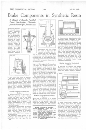
Vacuum Control Valve for Trailer Brakes,
AN improved valve for the control of suction-operated° trailer brakes (which was dealt with in our issue dated December 17, 19371, is shown in patent No. 506,809, by M. Johnson, /34-6, Ealing Road, Wembley. The valve is intended for use with a system employing a vacuum tank on both tractor and trailer.
As shown in the drawing, the engine intake pipe connects, via the pedal valve, with a closed chamber (5), whilst the port 4 leads to the servomotor. The bore 3 is piped to the vacuum tank, whilst bore 2 is open to the atmosphere.
In operation, engine suction on the diaphragm (1) normally keeps the servo-motor port (4) open to the atmospheric port (2). When the pedal is depressed, the vacuum is broken, the diaphragm lifts, the atmospheric port (2) closes and the port (3), which communicates with the vacuum tank, is opened up to the brake line (4). The storage vessel is kept permanently exhausted by a separate connection to the engine intake.
Improved Scavenging for Two-strokes.
DATENT No. 506,583 illustrates the I Continental trend towards twostroke engines, as disclosed by Auto Union A.G., Chemnitz, Germany. One of the major problems, in two-stroke design, is the efficient scavenging of the cylinder, and to improve this is the object of the present invention.
The drawing shows the engine cylinder, which is fitted with a large exhaust port (2) on one side and a somewhat smaller inlet port on the opposite side, both being controlled by the piston. The essence of the patent is the form of the inlet port; this is located at a sharp angle to the cylinder wall and is provided with a curved entrance wall (1). The exact shape of this curve (aerofoil) is of importance, its object being to cause the incoming gas to cling to the cylinder wall and thus reach the extreme top of the cylinder.
A Mixing Device for Coal-dust-fuel Engines.
"THE use of coal-dust, as an engine I fuel, is being investigated in many countries at the present time, and patent No. 506,982 shows a design for a dust-air mixing device. The patentee
is Hannoversche Maschinenbau-A.G., Hannover-Linden, Germany, a company better known as " Hanomag."
The device shown in the drawing has three apertures—an air inlet (7), a dust inlet (1), and the engine intake (4). A proportion of the air entering the air inlet (7) passes through perforations (2) and picks up the fuel, meeting the rest of the air at the bottom of the tube. From this point the mixture is whirled, first through a neck (3), then up an annular space (6), finally descending into the space (5). The cross-section of the mixing tube is of gradually increasing area, so that the mixture is loosened before being admitted to the engine. • Heating System for Double-deck Vehicles.
AMEANS for utilizing the engine radiator water for warming the interior of a bus, forms the subject of patent No. 507,011, from H. Metcalfe,
14, Cliffe House Road, Sheffield. In this design, water from the engine jacket is circulated around piping in the vehicle, flowing up the pipe (3) around the top deck, descending via pipe 1 to the lower-deck system, finally returning to the level of the bottom of the radiator. A thermostat (2) controls the temperature by diverting the engine water to the radiator or to the body heating system as required.
A feature of the patent is the inclusion of the inverted-U bends (4).