


A Timken Self-aligning Bearing
Page 66
If you've noticed an error in this article please click here to report it so we can fix it.
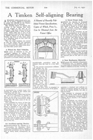
A BEARING which should prove useful in heavy vehicles is described In patent No. 330,349 by the Timken Roller Bearing Co., of America.
The drawing shows so plainly the working of the bearing that little else is needed in the way of explanation. The inner ring is curved to a radius struck from a point as indicated. Each roller has a part of its length curved to suit the inner ring, but is slightly tapered, as in the ordinary Timken, the lines of this taper going to a vanishing point in line with the axis of the shaft.
The two outer members are curved to suit the rollers and are• separated by a third member, which acts as a thrust to prevent the rollers from straying from their proper path.
A Wheel for Rail Vehicles.
THE name of Michelin et Cie, of France, appears in patent No. 349,890, which relates to ,a wheel carrying a resilient tyre which may be -either pneumatic or of solid rubber, and which
is surrounded by a metal tread (11 bearing the weight of the vehicle and contacting with the rail.
To prevent such a wheel from leiving the rail it is necessary to provide a flange on one side, as in railway practice, and it is in the construction of the flange that the main point of the invention lies.
Two examples are shown of how the arrangement may be carried out, that on the left being one in which the fiange is attached to the metal tread and has behind it a check ring (13) which limits its movement sideways.
The example on the right shows the flange attached direct to the wheel. The flange is formed of three parts, A, B and C, A being a continuous metal ring, whilst B is a ring of yielding material, such as rubber, and C a series of metal plates which contact with the side of the rail.
An Auxiliary-spring Device.
SPECIFICATION No. 349,582, by G. Carwardine, 17, Macaulay, Bath, points out that with ordinary springs a comfortable periodicity can be obtained only at heavy loads, consequently an B48 uncomfortable periodicity must be endured when the load is a very light one.
In the present arrangement ordinary leaf springs are employed, but at one end they are separated by two metal plates (13 and 13e), which are hinged, one to the dumbiron, and one to the leaf spring ; they are also held in contact with each other by means of two springs (13b), and are pivoted to the link (130) itt both ends. A block of fibre (13e) is intended to prevent lateral movement of the plates.
A Novel Front Axle.
PATENT No. 349,153, by Kirkstall Forge, Ltd., A. Aylwin and P. R. Cowell, describes a new form of front axle which is forged as a solid piece, then the central portion is drilled through from end to end, thus forming a light and strong axle.
The object of the invention, as set out in the specification, is to produce an axle which will resist both stresses of the usual kind caused by the weight to be carried, and those due to such circumstances as driving against full lock in deep sand where a very great horizontal strain has to be borne by a front axle, and to resist which the usual fl-section is not well adapted.
To make it possible to drill through the axle, the end Portions which carry the steering pins are raised slightly higher than usual. We should imagine that it would be difficult when drilling a hole of such length to ensure it keeping central with the external part of the axle at every point.
A New Raybestos Material.
THE patent, No. 349,919, of RaybestosManhattan, Inc., of America, relates to a new form of brake-facing material, which is claimed to be long wearing, to
maintain a constant and uniform coefficient of friction during its whole life and to: be slightly flexible, but able to hold its rivets.
. The material is composed of the follewing lb. rubber, 46 lb. asbestos fibre, 4 m: magnesium carbonate, 10 lb. litharge, 25 lb. barytes, 5 lb. sulphur; total, 100 lb.
These ingredients are mixed in an ordinary dough mixer and are extruded through a die. The principal claim reads as follows :—The process of producing a friction material for a friction element suitable for automobile brakes, clutches and the like which comprises mixing together fibrous asbestos and a hardenable binder into a readily malleable mass with the fibres distributed through the same, extruding the mass through a suitable die, thereby produce ing a continuous unlaminated strip of the cross • section desired, surfacetrowled on all sides by the action of the die and with the fibres in the interior thereof running in substantially all directions, drying the product, thereby producing 'a flexible porous mass of somewhat greater thickness than that of . the completed article, and compressing and hardening the same into a hard, dense article of the desired shape.