


A NEW FORM OF UNIVERSAL COUPLING.
Page 32
If you've noticed an error in this article please click here to report it so we can fix it.
A Résumé of Recently Published Patent Specifications.
MHE form of universal coupling which will permit of an error of angle or tilting of the two shafts 'which it couples is well known, and usually consists of spiders with three radial arms projecting from bosses which are connected to the ends of both shafts. Between these arms is fixed a flexible flat disc, which will permit the shafts to assume a tilting position in relation with each other, but such a coupling will not accommodate itself to a lateral displacement of the shafts—that is to say, shafts which, although they may be parallel axially to each other, are not in the same plane—one below the other. In cases where such an error as this may occur, it has been found necessary t) fit two separate flexible couplings— one at each end of a short, floating shaft. The present invention, by C. M. Utley, of London, described in specification No. 235,396, provides a cOupling which will accommodate itself to such an error without the floating shaft and with the use of one coupling only.
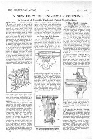
So far as we know it is the only flexible coupling which will accomplish this. The accompanying drawing shows diagrammatically the principle of the coupling. Two spiders are fixed—one to
each shaft—each having two radial arms only. Surrounding these radial arms is the flexible fabric, which is in the form of a flat belt attached in four places to the arms as shown diagrammatically.
Two-members act as spreaders, holding ant the belt until it forms a square. When A is the driver and is revolving in the direction of the arrow, the portions of the belt (B) and (0) transmit the drive from one set of radial arms to the other, the spreader (B) being in compression, whilst the other portions of the belt (E) and (F) and the spreader (G) are idle. Should the direction of rotation be reversed the portions (E) and (E) will take up the drive, and the spreader (G) will be in compression, whilst all other parts will be idle. Should any lateral displacement of the shafts be present, the flats formed by the belt, being of flexible material, can assume the form of a bow to a limited extent in either direction, and thus allow of such misalignment as would occur when an engine is coupled C48
with one coupling only to a gearbox, so saving the weight, cost and flywheel effect of the usual two couplings and floating shaft. Owing-to the flexibility of the belt a slight tilting of the shafts is permissible, although we understand that the coupling is not intended to be used behind the gearbox for transmitting the drive through a propeller shaft.
An Improved Frictionless Steering Gear.
1T has been found in steering gears where rollers impinge upon a worm that, owing to the fact that a car is usually running in a straight line more than in any other direction, the continual pressure of a roller on the part of the worm which it contacts with
when running straight will induce the formation of a hollow or depression at that spot. In the present invention (specification No. 235,298, the Daimler Co. and Jr. Nixon, of Coventry) more than one roller is always in contact with the worm, whilst in some positions as many as three rollers may contaet with the worm. To economize space and to enable more rollers to be used the roller bearings upon which the rollers themselves are mounted are sittP, ated behind the rollers, and not within them. A Plate. Clutch without a Sliding Presser Plate.
THE Sunbeam Motor Co., Louis Coat
alen and H. Stevens show a clutch in their specification No. 235,358, in which a flexible ring, made of leather, cotton or other suitable material, is employed in place of the usual sliding arrangement to allow the presser plate to move towards and away from the central disc. It will be seen from the illustration that A iS the flywheel, which is provided with an overhanging flange at its outer edge, to wbich is firmly attached the ring (Al). B is the usual , disc which is mounted on the shaft, and drives .by, means of splines. C is the presser plate, audits only attachment to A.1 is by means of the flexible ring (D). Springs of the usual type are shown for causing the necessary pressure between C. and A.
An Improvement in Ford Axles. SPECIFICATION No. 235,480, by Charles Baxter, shows a means of fitting an extra roller bearing to the rear axle of a Ford. It will be seen that the inner ring of the roller bearing is mounted on the extending end of the Axle tube, _whilst the outer ring is housed in a member attached to the brake drum. Holes are provided to enable the outer ring to be forced out of its housing when renewals are required.
A New Alloy for Brake Linings.
NKITCHEN, of Aachen, in his . specification No. 235,473 describes an alloy which, he claims, has great resistance to wear, and, although more costly than cast-iron, will in the long run prove to be a more economical material, as renewals will not be needed so fro: quently. The alloy consists of copper 58-64 per cent., sine 32-38 per cent., manganese 0.5-2.5 per cent., iron 0.5-2 per cent. and aluminium 0.01-2 per cent. He says that the alloy can be worked and bent whilst in a cold state, and that it will, work satisfactoi2y against a steel drum.