


Brake-proportioning Valve with Adjustable Ratio
Page 44
If you've noticed an error in this article please click here to report it so we can fix it.
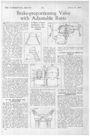
A Résumé of Patent Specifications That Have Recently Been • Published AVALVE for controlling the ratio between any two sets of air-operated brakes is shown in patent .No. 556,800 by Bendix-Westinghouse Automotive Air Brake Co., Elyria, phi!), U.S.A. The device may be used between the front and rear brakes of a single vehicle or between separate vehicles, such as a
tractor and its trailer. The chief feature is that for low braking efforts, all wheels are equally braked, hut increased effort puts an extra load on one set or the other, the extra load being adjustable by means of a simple control.
Referring to the drawing, air from the pedal valve (12) passes into pipe 3, which supplies the rear (or trailer) • brakes (7). The front (or tractor) set• (13) is supplied from pipe 11, whilst compressed air is ied to the valve via pipe 10.
In operation, air from the pedal valve enters the diaphragm chamber (4)., at
the same time operating the rear brakes directly. The diaphragm is forced downwards and its action is transmitted via lever 2, a precompressed spring (.1), And a second lever (8), which presses on a lower diaphragm. Movement of the latter causes a double ball-valve (9) to close an atmospheric poit and open the bottom pressure port to the brake line ,(11).
Note that the preconipressed spring (1) acts as a solid member with 'slight brake applications, but if the applied pressure he great enough, it would be further compressed. When this occurs, the movement of lever 2 is conveyed to lever 8 by a disc (5), which acts as a distance piece. By moving this to the left or right, the ratio between the two levers can easily be varied,. which makes itself felt as a variation between front and rear braking. An outside knurled knob (6) enables the driver rapidly to make any required adjustment.
AN OH. RECLAIMER FOR GARAGE USE
ApEVICE of interest to operators using a number of vehicles is shoWn in patent No. 557,039, by C. Vokes,. 95-105, Lower Richmond Road, London, .W.15. It describes an oil reclaimer for engine oil, which is suitable for use in any place where a compressed-air supply is 'available.
The apparatua is divided into two main parts—a gravity-operated 'filter for removing the coarser impurities and a final filter employing compressed air to expedite the floW. Refuting to. the drawing, the dirty dil is poured into the top of a Container (8) and occupies the space on the outside pi a .coarse filter (7). The oil slowly percolates into the centre space, whence. it drops
A34 through into the wer chamber. When sufficient oil has collected there, a cut-off valve (6) is closed a n d
compressed a it admitted via cook 5. The oil is then forced. up through a pipe (4), past an
electric heater' (9) into the upper space of the second unit.
Being now under pressure, it is driven through a fine filter pack (1). This may be composed of a number of substances, one being campressed sawdust which can afterwards be used for fuel purposes. The clean Oil is finally drawn off from cock 3, whilst an upper cock (2) fonns an outlet for sludge. By leaving valve 6 open and turning on the compressed air, filter 7 can be cleaned, the air dislodging the foreign matter from the outside of the filter element.
A ROTARY VALVE OF IMPROVED DESIGN 'pATENT No. 556 m
,740 conies from a pioneer of novel engine design—F. Aspin, 149, Walmersley Road, Bury, Lancs. ' The subject is an improved design of rotary valve, to enable light alloy to be used for the construction, with a bearing surface of More durable metal. To achieve this, the valve housing and the valve itself are both laced with .good bearing metal, whilst the bulk. may be formed in magnesium alloy. The drawing shows the two parts; the valve (4) is the well-known Aspin-ported cone, covered-with a layer (3) of sprayed-on bronze. The housing (2) is also faced, this
3 time internally, with a layer of lead-bronze, chromium, or other durable metal.
The exterior of the housing • is stepped as shown at 1 and the cylinder head is correspondingly stepped.
REDUCING OIL-ENGINE PISTON TEMPERATURE
I MPROVEMENTS in the, combustion
head of an oil engine form the subject of patent .No. 556,982, from L. Gardner and Sons, Ltd., J. H. Gardner and J. H. Gardner, all of Barton Hall Engine Works, Patricroft, Manchester. The object is to produce a. shape that will minimize the transmission of heat to the piston crown.
The combustion space in the head is in the form of a hemisphere, the valve heads being made concave to blend-in' with the general outline. The essence of the patent is that the diameter of the hemisphere is considerably less than that of the cylinder bore, a fact which promotes two . desirable results, one being the creation of a powerful " squish," as the piston approaches the step, whilst the other is the -reduction in that area of the piston Which is subject to the greatest flame intensity.