


Patents Completed.
Page 18
If you've noticed an error in this article please click here to report it so we can fix it.
Propeller-shaft. Novel Change-speed Gearind. Carburetter Improvements. Additional Spring Suspension.
Complete specifications of the patents published on this pate can be obtained from the Sales Branch, Patent Office, Holborn, 1,V.C., at the cost of sixpence for each specification.
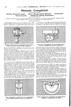
THE DAIMLER CO. LTD. and A. E. BER.RIMAN, No. 5609, F. J. HADFIELD, No. 3366, dated 9th February, 1914.—This dated 5th March, 19l4.—The objects of this invention are to gearbox is one in which the gears are brought into mesh by provide a construction of propeller-shaft casing which allows a movement of the wheels in their own plane so that double
the use of large flexible couplings at the forward end of the propeller shaft and more particularly to provide accommodation for two such couplings.
Instead of using the ordinary spherical joint, the forward end of the casing is articulated to the framework by a spherical joint which is eccentric from the propeller shaft. A bracket extends forward from one side of the propeller-shaft casing and it carries a spherical head received in a socket secured on a transverse frame member. The flexible couplings are arranged one at each side of this frame member ; the division of angular movement between the two couplings reduces their working movement and results in considerable saving in the life of both of them.
G. N. TRA VERS, No. 10,662, dated 6th November, 1913.—In this carburetter the fuel chamber lies within a casing through which heated air is supplied, and it has another air passage passing centrally through it. At the top of the fuel chamber there is a conical collar perforated to allow the passage of heated air into the mixing chamber above it and a central flange on the collar which fits within the fuel chamber and has tapered grooves in it to serve as fuel jets.
These jets are controlled by a sleeve having similarly tapered grooves arranged opposite each of the first set of grooves. This sleeve has a mushroom head to form the top of the mixing chamber, and is adjustable.
This controlling sleeve fits over the central air inlet and is provided with a number of small holes by which additional air can enter the mixing chamber. The mixture passes away from the side of the mixing chamber by a number of holes. helical gearwheels can be used and the rounded corners, now used with straight toothed wheels are rendered unnecessary
The countershaft is mounted in a separate frame inside the gearbox and this frame is pivoted near the bottom so that it can be swung to carry the countershaft away from the driving and driven shafts to disengage the gears.
The gear ratios are changed in the ordinary manner by sliding gearwheels or by clutching suitable wheels to the various shafts, and when the wheels have been set, in the required position the countershaft is swung forward to bring the various wheels into mesh.
An auxiliary hand-lever is provided to control the movement of the countershaft-frame, and this, of course, requires operation when changing gears, but time is saved since the gears may be brought. into mesh while there is still some motion in the driving shaft with but little risk of injury.
BOTILTRER 13RooKs and J. HoLa., No. 29,458, dated 22nd of December, 1913.—This specification describes a construction of spring suspension which is intended to absorb vibration or shock due to inequalities of the road surface. The axle is carried on an ordinary semi-elliptic spring, and each end of the spring is connected to one end of a rigid lever, the other end of which is pivoted to a bracket on the chassis frame. An inverted semi-elliptic spring is mounted on the chassis and its ends are arranged to bear on pins at about the middle of the length of each of the levers.
The two levers are actually floating levers, and their tendency is to rock about some point within their length and draw the vehicle frame down when the wheel is raised.