


A Self-energizing Disc Brake
Page 70
If you've noticed an error in this article please click here to report it so we can fix it.
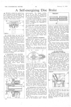
riA BRAKE in which the applied force is amplified by the movement of the disc is shown in patent No. 788,841. It is so arranged that it will function equally well in either direction of rotation. (L. Coatalen, 7 Rue Lesueur, Paris.)
The drawing shows the part of the mechanism that produces the self-energizing action. Spanning the disc (1) is a caliper-type housing (2) which carries the actuator, in this case, a hydraulic cylinder (3). One friction pad (4) is fixed to the caliper, the other to a thrust member (5) of the hydraulic piston.
The thrust member is permitted some lateral freedom so that it can move with the disc. With this movement, rollers (6) make contact with sloping ramps and tend to push the pad more forcibly into contact with the disc. A similar arrangement provides identical action in the opposite direction of rotation.
A MAGNETIC FAN CLUTCH
AVEHICLE engine can sometimes be over-cooled, and patent No. 788,649 shows a radially compact clutch enabling the fan to be wholly or partly disconnected when conditions demand. (Warner Electric Brake and Clutch Company, 449 Gardner Street, South Beloit, Indiana, U.S.A.)
The unit is mounted on a stationary tubular member (1). The driving pulley is carried on the central spindle which runs on ball-bearings (2). Freely journailed on ball-bearings 3 is the hub (4) of the fan blade assembly.
The driving connection between the two comprises an armature ring (5) supported from the fan boss by springmetal strips (6). The armature is attracted to the annular pole faces (7) of an electro-magnet. The magnet winding (8) is, for the sake of compactness, located remotely from the pole faces and the two pole members are separated by a non-magnetic packing (9).
A facing of friction material is lodged between the poles to take the wear of partial engagement. The inner magnetic circuit is completed by a stationary Lsection core (10).
AN INJECTION PUMP MOUNTING
PATENT No. 785,923 gives details of a method of mounting the injection pump on an engine. It is carried on a bracket of box-section in which an idler gear is journalled. The idler connects a pinion on the pump with one on some moving part of the engine such as the camshaft. (C.A.V., Ltd., Warple Way, Acton, London, W.3.)
POWER-ASSISTED STEERING
HYDRAULIC assistance for steering forms the subject of patent No. 788,731. The servomotor used in the system is of the swinging-vane type. (W. Briggs and Burman and Sons, Ltd., Wychall Lane, King's Norton, Birmingham, 30.)
Referring to the drawing, the vane (1) oscillates in a part-cylindrical bearing (2), whilst the other end sweeps over a closefitting curved surface (3) to vary the volume of the space on each side. The drop-arm is connected to an extension of the vane spindle.
Constantly circulating hydraulic fluid enters the port 4, and after passing through a trunnioned valve member (5) returns to the supply. The screwed spindle carries a nut (6) which, if turned through a few degrees, obstructs the fluid flow, so that it is pumped into one closed chamber and drawn from the other, causing the vane to move. The nut is spring-biased into the neutral position so that the action is self-cancelling.
The screwed spindle is not integral with the steering column, because it has to be able to rock slightly about the spherical bearing (7), but it is connected thereto.
AN IMPROVED CLUTCH PLATE IMPROVED clutch plates form the sub]. ject of patent No. 789,287. The improvement is partly in the design of the plate and partly in the materials used for the friction lining. (S.A. Francaise du Ferodo, 64 Avenue de la Grande Armee, Paris 17.) The drawing shows a scrap view of part of the proposed plate. Friction facing is cut away by grooves (1) to form numerous segments, and the grooves extend into the central metal plate. They are shallow near the hub and deepgn towards the edges where they may break through to form slots. Irregular spacing is preferred to prevent resonance, with consequent chatter and squeak.
The friction facings are of two kinds, placed in diametrically opposed groups. One is a conventional asbestos-filled phenolic resin, with brass reinforcement. The other material is a sintered bronze having graphite added, and possibly some lead.
The asbestos facings, being somewhat resilient, come into operation ahead of the others, but the metallic facings operate principally tinder heavy load. The latter are, however, subject to fading under heat, and in this event the drive is maintained by the asbestos.
AN OIL ENGINE COMBUSTION SCHEME
ATREND in combustion chambers for oil engines is to arrange for the fuel to be thinly sprayed over the walls of the chamber; this, in conjunction with a vigorous air swirl, is said to give smoother and better combustion. A chamber of this nature forms the subject of patent No, 789,423. (Daimler-Benz A.G., Stuttgart-Unterturkheim, Germany.)
The drawing shows a typical layout in which the combustion chamber is located in the crown of the piston. The chamber (1) is conical in form, and fuel is injected in the region of the smallest diameter and at an oblique angle.
Air swirl is provided in this case by a shrouded inlet valve (2), although other means may he used.
The slope of the injector (3) is such that the fuel is sprayed over the upper part of the conical face, the increasing diameter causing it to thin out as it descends.