PATENTS SUMMARIZED.
Page 22

If you've noticed an error in this article please click here to report it so we can fix it.
A Simplified Ignition System.
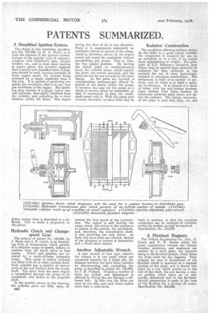
The object of this invention, specification No. 107,388, by M. A. Violet, is to limit the expense of the ignition system. Instead of the popular type of magneto, complete with distributor gear, contact breaker, etc., and in most cases running at engine speed, this inventor suggests that a special and simplified form of magneto should be used, running normally at twice engine speed, the current being collected by a single conductor from a slip ring. It is capable of producing two sparks per revolution, that is to say, four per revolution of the engine. The spark-mg plug consists of a single, heavy central electrode, thoroughly insulated from the cylinder, and projecting for a short distance within the latter. The engine piston carries what is described as a deflector. This is really a projection on
the piston. .
Hydraulic Clutch and Changespeed Gear.
The subject of patent No. 112,536, by J. Healy and A. E. Carter, is an interesting form of transmission which permits of a coariplete lenge of speeds, infinite in number, from the direct drive to free, engine. Clutch and gearbox are replaced by a multi-cylinder hydraulic pump. This pump is totally enclosed and filled with oil or other suitable fluid. Each cylinder has a number of narrow ports at the end furthest from the crankshaft, The drive from the main engine is transmitted through the pump to its crankshaft, and thence to the propeller shaft.
In the position shown in the drawing, the cylinder ports are fully open, alC52 lowing free flow of oil in any direction. There_ is in consequence practically no resistance offered to motion of the pump, which is, therefore, driven by the engine round and round it crankshaft Without transmitting any power. This is, then, the free engine position.. By moving the clutch pedal or clutch-operating lever, the cylinder liners, which contain the ports, are moved outwards, and the ports are one by one covered by the main casing. As the ports are covered, a corresponding (resistance ii,s offered to motion of the piston within the pump, it becomes less easy for the pump as a whole to revolve about its crankshaft, so that it commences to drag the crankshaft round with it. With one pump port covered, therefore, we have what may be termed the first speed of the transmission. The engine is still driving the pump round, but owing to the resistance to motion of the pistons, the crankshaft, and, therefore, the transmission shaft, is also revolving, but only slowly. As more and more ports are covered, motion of the plungers or pistons is impossible, and a, direot drive ensues.
Another Adjustable Wrench.
A pipe virench of that type wherein the wrench is in two parts which are connected together by a single pin, the distance between the jaws being variable by disconnecting and ,recoupling the parts, is described in patent No. 112,603, by J. H. Pickard. Usually a number of holes are drilled, and adjustment is effected by fitting the pin through a different hole. In this case the holes are open at one side, and each forms rather more than a semi-circle.
Radiator Construction.
The conditions affecting radiator design do not differ to a great extent whether the component is required for use on an aeroplane or on a car, if we except those appertaining to weight. The principle of L.T. Delaney's invention may before long be applied more generally to radiators for cars, although at the moment its use is more particularly adapted to aeroplane construction. The component is built of a number of sections, each of which is in itself a radiator in minature. It is formed of a block of tubes, with top and bottom headers, pipes leading from these headers to transverse sectional pipes above and below the radiator. The design, moreover, of the pipes is such that they, too, are built in. sections, so that the complete component can be enlarged. or reduced, section by section, as may be required. Specification No. 112,043.
A Flywheel Magneto.
The Villiers Engineering Co. Ltd., G. Funck and F. H. Farrer adopt the _usual construction wherein the contact breaker, armature, and condenser are carried by a back plate, the magnets being in the flywheel proper, which forms the front cover for the magneto. They arrange for ease of detachment of the flywheel which is mounted on a tapered portion of the shaft, and is drawn into place by a nut which screws on to the end of the shaft, the nut having a conical portion which bears on an Outwardly chamfered hole in the flywheel. Special preparation is made in the bore of the flywheel for a forcing off screw. Specification No. 112,529.


