


Patents Completed.
Page 28
If you've noticed an error in this article please click here to report it so we can fix it.
BURNER.—Wright.—No. 18,206, dated 14th August, 1906.—The burner has a central longitudinal passage (1) of rectangular cross-section, and, at one end, is a funnel-shaped air inlet (2). In the floor of the longitudinal passage is a fuel ad
mission orifice (5), and, in front of this, a projection (4) is provided so that the incoming air does not sweep directly across the same. On the top and bottom of the passage (1), wedge-shaped steam chambers (6, 7) are provided, having narrow outlets (8), whereby the issuing fuel and air is thoroughly atomised and co-mingled.
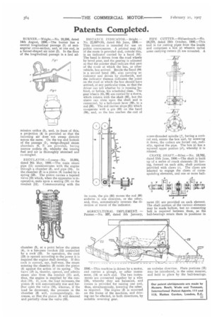
REGULATOR.—Lorenz—No. 10,894, dated 9th May, 1906.—The main steam pipe (11) communicates with the engine through a chamber (3), and pipe (14). In the chamber (3) is a piston (4) loaded by a spring (23). The piston carries a tapered valve (18) which, when the apparatus is inoperative, rests upon a seating (10) on the conduit (11). Communicating with the
chamber (3), at a point below the piston (4), is a bye-pass conduit (12) controlled by a cock (13). In operation, the cock (13) is opened according to the power it is required the engine shall develop. If this cock is opened, say, half-way, the steam entering the chamber (3) raises the piston (4) against the action of its spring. The valve (18) is, thereby, opened, and admits steam also from the conduit (1I) and, thus, the engine is supplied by the conduit (14). if, now, the load increases, the piston (4) will automatically rise and further open the valve (18), whereas, if the load be decreased, the pressure in the chamber (3) will, correspondingly, decrease, so that the piston (4) will descend and partially close the valve (18). DISTANCE INDICATOR.—Bright.— No. 22,8975/05, dated 8th June, 1906.— This invention is intended for use cm public conveyances. A printed map (A) of the route is provided and, outside this, is an indicator carried by a band (84). The band is driven from the road wheels by bevel gear, and the gearing is adjusted so that the pointer shall indicate that part of the route at which the bus, or other vehicle, has arrived. Beside the sand (84) is a second band (93), also carrying an indicator and driven by clockwork, and the indicator thereon indicates the point on the road at which the bus should have arrived, at any particular time, so that the driver can tell whether he is running behind, or before, his scheduled time. The gear wheels (85, 86) are carried by a sleeve, which rotates with the shaft (88), but the sleeve can slide upon the shaft and is connected, by a bell-crank lever (89), to a rod (90). The rod carries stops (91) which co-operate with a pin (92) on the band (84), and, as the bus reaches the end of
its route, the pin (92) moves the rod (90) endwise in one direction, or the other, and, thus, automatically reverses the direction of travel of the indicator.
AGRICULTURAL IMPLEMENT. — Painter.—No. 337, dated 5th January, 1906.—This machine is driven by a motor, and carries a plough, or other instrument, (14) at each end. The two instruments are connected together by a wire (28), whereby they are balanced, and means is provided for raising one and, thus, simultaneously, lowering the other. as required. The engine (3) is mounted on the frame of the machine, and driving can be effected, in both directions, by suitable reversing gear.
PIPE CUTTER.—Hillseribusch.—No. 23,178, dated 19th October, 1906.—This tool is for cutting pipes from the inside and comprises a box (e) wherein radial arms carrying cutters (b) are mounted. A
screw-threaded spindle (f), having a conical end, enters the box and, by screwing it down, the cutters are forced out, _radially, against the pipe. The box (e) has a squared upper portion (el), whereby it is rotated.
CRANK SHAFT.—Riley.—No. 13,7e2, dated 15th June, 190B.—The shaft is built up of a series of crank elements (B) having, formed on each side, shaft portions provided with claws (r). The claws are adapted to engage the claws of corresponding elements, and one or more ball.
races (D) are provided on each element. The shaft portion of the various elements may be made hollow, but no connecting belt is required between them, as the ball-bearings retain them in positions in an endwise direction. Plain portions (H) may be introduced, in the same manner, and held in place by the ball-bearings.