The B.T.H. Petrol-Electric System.
Page 25

If you've noticed an error in this article please click here to report it so we can fix it.
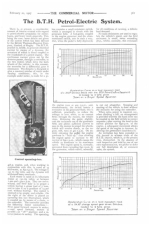
There is, at present, a considerable amount of interest evinced with regard to petrol-electric propulsion for motorbuses, and heavy work generally. This being the case, some details are given of the system which has been devised by the British Thomson-Houston Company, Limited, of Rugby. The B.T.H. practice is, briefly, to generate electrical current by means of a dynamo, the armature of which is direct coupled to the crankshaft of a petrol engine. The continuous current given out by the dynamo passes, through a controller, te the two motors which drive the back wheels of the vehicle : in this manner, thc necessity for a differential gear is eliminated. The dynamo is designed to give a constant number of watts under varying conditions; this, in the example under notice, is made for a 30 4oh.p. engine, and, when working in conjunction with this, is rated at 15 kilo-watts, at 85o r.p.m. The voltage is 130 to 165 volts, and the dynamo will withstand heavy overloads.
Each motor is rated at 71 kilo-watts (input at 130-165 volts), at between 1,40o and 1,50o r.p.m. They are serieswound, and their duty is to propel a vehicle having a gross load of 7 tons, and to take it up a gradient of 14 per cent. without heating. The control is claimed to be simple, and reliable. On the right of the driver is placed all operating box (see illustration), which is coupled up, by means of a chain, in the controller. The controller provides the following motor connections :First speed forward, motors in series; second speed forward, motors in parallel ; an " off " position ; and a reverse (motors in series). The operating box contains a small resistance switch, which is arranged in circuit with the generator field. A foot-pedal, coupled to the engine governor and the aforementioned switch, acts in such a way, that, when the pedal is fully 'depressed, the engine runs at 400 r.p.m., and, simultaneously, the switch inserts a resistance in the generator field ; this is sufficient, practically, to reduce the voltage to zero, when, as no current flows through the motors, the vehicle stops. Releasing the pedal, slightly, cuts the resistance out of the generator field, and allows sufficient current to pass to the motors to propel the wheels, which will revolve slowly, as the engine, still, runs at ,plo r.p.m. On entirely releasing the pedal, the engine governor is " held up," thus allowing the engine speed to increase to the normal of 8so r.p.m., which causes the vehicle to accelerate to its maximum speed. The engine speed is, normally, revented from exceeding 850 r.p.m. by he generator, which exerts, normally, for all conditions of running, a definite load demand.
No main resistances are used to regulate the vehicle's speed, and the field resistance is small, never exceeding whilst, normally, this resistance is cut out altogether. Stopping and starting of the vehicle is done without the necessity for using the controller.
When extra power is required, say, when climbing a hill, an arrangement is provided whereby the hand lever can be coupled to the field switch in correct sequence; after moving the level to the correct position for 85or.p.m. of the engine, a subsequent movement allows the speed of the engine to increase, by altering the generator's load-demand.
An invitation has been extended to this journal to witness trials of the B.T.H. chassis, which is, at the present time, dismantled. In the absence of .i.tch inspection and trial by one of our own representatives, we prefer to defer any full description of, or comment upon, the system.


