


Centrifugal Clutch in Hydraulic Coupling
Page 60
If you've noticed an error in this article please click here to report it so we can fix it.
HYDR AULIC couplings are often 1 1 provided with some form of straight-through lock, and a device of this nature forms the subject of patent No. 760,249 (Self-Changing Gears, Ltd., Lythalls Lane, Coventry).
The drive in this case is provided by an automatic centrifugal clutch, the form of which is particularly suitable for building into the rather restricted space available in a hydraulic coupling.
The coupling shown works on wellknown principles, the novelty being that it contains four clutch shoes 11) faced with friction material on their working faces (2). These faces are preferably grooved circumferentially to increase the contact surface.
Each shoe is pivoted at one end on a pin (3) and each pin is carried in a small sliding block, so that the shoes not only rock but can also move bodily outwards. In doing so they press on their enclosing member and so transmit the drive. Retraction is performed by a spring (4) surrounding a channel cut in the four shoes.
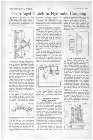
A NEW TYPE OF TIMING CHAIN
ANOVEL design for a timing chain is disclosed in patent No. 758,103. (A Flocke, Wupperhof 2, Solingen, Germany.) The advantages claimed
are quietness, less wear and the ability to resist stretch.
As will be seen from the drawing, the links (1) are made semicircular so that at no time do they make contact with the sprocket. This means that only the rollers meet the sprocket and they are comparatively frictionless. To locate the chain in an endwise direction, A34 a recessed overhanging washer (2) is fitted at. each end of the rollers.
Although not mentioned in the patent, the chain would possess a slight springiness due to the resilience of the semicircles in tension.
A NEW FILTRATION PROCESS
THE two systems of oil filtration, full-flow and by-pass, each have their advantages, but neither can be claimed to be the perfect method of cleaning engine-oil. A scheme claimed to be nearer the ideal is shown in patent No. 760,204 (A.B. Scania-Vabis, SUclerttilje. Sweden).
The scheme is basically one of the by-pass variety, but the Oil from the pump is first centrifuged, and only the cleaner fraction is directed to the bearings, the remainder being fed to a filter.
The drawing shows a diagrammatic layout in which the pump, (1) draws oil from the sump and delivers it into a cyclone chamber (2). The rapid spin created by the tangential inlet throws the impurities to the walls, leaving the centre core of oil reasonably clean. This oil is fed to the bearings via pipe 3.
The unclean oil drains down the walls of the cyclone chamber and passes through a filter (4) before reaching the sump. Unit 5 is the usual release valve for excess pressure.
BALL BEARINGS IN LIGHTALLOY HOUSINGS A BALL-BEARING outer race 1-1 should he a good fit in its housing, but when the latter is made of aluminium alloy the problem of differential expansion arises. It means that the fit will tend to be either tight when cold, or slack when hot. To overcome this is the aim of a scheme disclosed in patent No. 760.145 (l'Aluminium Francais, 23 Rue Balzac, Paris 8e.).
As shown in the drawing, it is pro posed to interpose a thin sleeve (1) of plastic material. It may be moulded around the bearing as shown, or instead can be moulded into a channel in the housing.
A polyamide plastic is preferred (nylon for example) but any substance will do provided that it has a co
efficient of expansion higher than that of aluminium and a modulus of elasticity below that of the metal.
The excess diameter of the plastic should be about 0.015 diameter for aluminium and 0.02 diameter for magnesium. The specification gives details of the mathematical approach to specific cases.
A NEW INJECTION PUMP
AROTARY-DISTRIBUTOR injection pump is dealt with in patent No. 760,283 (Clayton Dewandre Co., Ltd., Titanic Works, Lincoln). A feature of the design is that the rotary distributor has an additional reciprocating movement imparted to it, the aim of which is to reduce the likelihood of scoring and to simplify the porting problem.
Referring to the drawing, the pump unit (I) is fairly conventional and works on well-known principles. The .output from its single plunger is led via pipe 2 to the distributor unit. This comprises a ported rotor (3) driven via bevel gears (4) from the camshaft. As the rotor turns, its ports line up in succession with the injector outlets, one of which is shown at 5.
The rotary drive is taken through a tongued coupling (6) which permits the rotor to rise and fall. This axial motion is created by a fixed in (7) which engages a sloping groove (8) in the rotor. Other methods of reciprocating the rotor are mentioned, including a swash-plate mechanism.