


Self-Feeding Carburettor
Page 50
If you've noticed an error in this article please click here to report it so we can fix it.
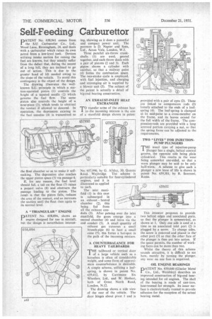
DATENT No. 658,941 comes from 1 the 511 Carburetter Co., Ltd., Wood Lane, Birmingham, 24, and deals with a carburetter which raises its own petrol from a low-level tank. Devices utilizing intake suction for raising the fuel arc known, but they usually suffer from the defect that, during the ascent of a long hill, they are inclined to go out of action. This is due to the greater head of lift needed owing to the slope of the vehicle. To avoid this contingency is the object of the design.
The drawing illustrates the wellknown S.U. principle in which a suction-operated piston (1) controls the height of a tapered needle (2) which governs the fuel flow. . The same piston also controls the height of a nose-piece (3), which tends to obstruct the venturi if allowed to descend. In operation, the depression existing in the fuel annulus (4) is transmitted to the float chamber so as to make it selfsucking. The depression also reaches the upper piston space (5) via passage 6.
If, for any reason, the fuel level should fall, a tail on the float (7) raises a poppet valve (8) and obstructs the passage leading to the piston. The result is that the piston falls, reduces the area of the venturi, and so increases the suction until the float rises again to its normal level.
A "TRIANGULAR" ENGINE
DATENT No 658,894, shows an engine designed for use in aircraft, but the design is nevertheless interest ing, showing as it does a powerful and compact power unit. The patentee is D. Napier and Sons, Ltd., Acton Vale, London, W.3.
Three parallel six-throw crankshafts (1) are used, geared together, and each throw deals with a pair of pistons (2 and 3). Each piston shares a cylinder with another, so that a midway point (4) forms the combustion space. The two-stroke cycle is employed, with fuel injection, and charging -and scavenging air is supplied by a blower unit (5).. The subject of the patent is actually a detail of big-end bearing construction.
AN EXHAUST-INLET HEAT EXCHANGER
TO transfer some of the exhaust heat to the incoming mixture is the aim of a manifold design shown in patent
No. 657,990, by G. AlIday, 30, Queens Road, Weybridge. The scheme is particularly suitable for four-cylindered engines, and it is illustrated as applied to such.
The inlet manifold (1) in this case is submerged in an exhaust heated chamber (2), this being fed from all the exhaust con duits (3). After passing over the inlet manifold, the gases emerge into a second chamber (4) and leave via the end conduit (5). A small quantity of exhaust gas traverses a small branch-pipe (6) to heat a small cone (7); this forms a hot-spot in the path of the incoming mixture.
A COUNTERBALANCE FOR HEAVY TAILBOARDS
THE tailboard or vertical door of a large vehicle such as a horsebox is often of considerable weight, and some form of approximate counterbalance is desirable. A simple scheme, utilizing a leafspring, is shown in patent No. 659,412. by Carrimore Six Wheelers, Ltd., and W. Herbert, both of Great North Road, London, N.12.
The drawing shows a side view of the rear of the vehicle. The door hinges about pivot 1 and is
provided with a pair of eyes (2). These are linked to compression rods (3) loosely attached to the ends of a leafspring (4). The leaf-spring is clamped at its mid-point to a cross-member on the frame, and its leaves extend for the full width of the frame. The compression-rods are provided with a long screwed portion carrying a net, so that the spring force can be adjusted to the requ irements,
TWO "LIVES" FOR INJECTIONPUMP PLUNGERS THE usual type of injection-pump plunger has a single, helical control groove, the opposite side being plain cylindrical. This results in the wear being somewhat one-sided, so that a worn plunger may be said to be only half-worn. A .scheme to give such a plunger a new lease of life is shown in patent No. 659,301, by R. Scorzoni, Rome.
This inventor proposes to provide two helical edges and associated ports, so that the plunger is symmetrical, as shown at I. Only one side is used at a time as an associated inlet port (2) is plugged by a screw. To change sides, the screw is removed and placed in the other port (3) so that the other face of the plunger is then put into action. If the space permits, the number of working faces can be more than two.
Whilst the theory of this scheme sounds attractive, it is difficult to see how, merely by turning the plunger, any wear on one face is negatived.
OIL ENGINE BEARINGS DATENT No. 659,640 (Glacier Metal 1 Co., Ltd., Wembley) describes an improved construction of big-end bearing intended for oil engines. The shell of the bearing is made of caSt-iron, heat-treated for strength. Its inner surface is electrolytically treated to provide adhesion for the reception of the actual bearing metal.