


Fuel-injection System for Petrol Engines
Page 42
If you've noticed an error in this article please click here to report it so we can fix it.
A Resume of Patent Specifications That Have Recently Been Published. Copies May Be Obtained from the Patent Office. Price 11Each
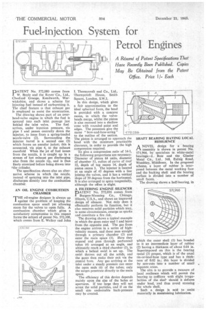
PATENT No. 572,080 comes from W. Boyle and the Rover Co., Ltd., Chesford Grange, Kenilworth, Warwickshire, and shows a scheme for injecting fuel instead of carburetting it. The chief feature is that exhaust gas is employed to assist the atomization.
The drawing shows part of an overhead-valve engine in which the fuel is sprayed into each inlet passage just
behind the inlet valve. The fuel arrives, under infection pressure, via pipe 1 and passes centrally down the injector, to issue from a spring-loaded nozzle-valve (2). Surrounding the injector barrel is a second one (3) which forms an annular jacket; this is connected, via pipe 4, to the exhaust manifold When the jet of fuel issues from the nozzle, it is caught up in a stream of hot exhaust gas discharging also from the nozzle tip, and is thus finely atomized before being drawn into the cylinder.
The specification shows also an alternative scheme in which the nozzle, instead of spraying into the inlet pipe, discharges directly into the combustion chamber.
AN OIL ENGINE COMBUSTION CHAMBER 9"HE oil-engine designer is always up 1 against the problem of keeping the combustion space small yet allowing room for the valves to open fully. A combustion chamber which gives a satisfactory compromise in this respect forms the subject of patent No. 572,100, which comes from E. Walker and John
1. Thornycroft and Co., Ltd., Thornycroft House, Smith Square, London, S.W.1.
In this design, which gives a fair approximation to the ideal spherical form, the head is provided with a concave recess, in which the valveheads merge, whilst the piston is also recessed into a shallow cone with rounded point and edges. The patentees give the name " bow-and-bow-string " to the outline of the section. The piston is arranged to approach the head with the minimum practicable clearance, in order to provide the high compression required.
To give a conipression ratio of 14-1, the following proportions are necessary: Diameter of piston 64 units, diameter of chamber 53, radius of curve of roof 32, depth of top recess 14, depth of piston recess 3. The injector is located at an angle of 45 degrees with a line joining the valves, and it has a vertical slope of 20 degrees from the horizontal. It is also arranged to spray tangentially, although the offset is slight.
A FILTERING ENGINE SILENCER
PATENT No. 572,036 comes from Burgess-Manning Co., Chicago, Illinois, U.S.A., and shows an improved design of silencer. Not only does it effectually perform its function, but it also removes solid particles which may, in some circumstances, emerge as sparks and constitute a fire risk.
The drawing shows a typical example in which the gases enter end 1 and leave from the opposite end. The gas from the engine arrives in a series of high velocity masses, and these pass straight through a primary chamber (2) and enter the main space (3). Here they expand and pass through perforated tubes (4) arranged at an angle, and ultimately reach a third chamber (5), in which a helical swirl is set up. The swirl throws out all the solids, and the gases then make their exit via the central bore. Any gas arriving at the inlet under a steady pressure can enter the open ends (6) of the tubes; only the surges penetrate directly to the main space.
The efficiency of this device depends mainly upon the size of the holes or apertures. If too large they will not arrest the solid particles, and if on the small size undesirable back-pressure may be created. SHAFT BEARING HAVING LOCAL RESILIENCE
ANOVEL design for a bearing assembly is shown in patent No. 571,966, by specialists in white-metal bearings—J. Bate and the Glacier Metal Co., Ltd.. 368, Ealing Road, Wembley, Middlesex. In the proposed scheme, a layer of rubber is interposed between the metal working face and the backing shell and the bearing surface is divided into a number of small facets.
The drawing shows a half-bearing, in which the outer shell (1) has bonded to it an intermediate layer of rubber (2) having a thickness of about 0.01 in. Superimposed on this is the bearing metal (3) proper, which is of the usual tin-or-lead-base type and has a thickness of 0.02 in.; this layer is divided by saw-cuts into a number of small separate areas.
The aim is to provide a measure of local resilience which will permit the bearing to cotiforn with slight irregularities of the shaf should it deform under load, and thus avoid stressing the whole shell.
Such a design is said to assist materially in maintaining lubrication.