


AUTOMATIC CHAIN SPEED GEAR.
Page 32
If you've noticed an error in this article please click here to report it so we can fix it.
A Résumé of Recently Published Patents.
A rather ingenious variable gear is described by R. Lindsay in specification -No. 153,538, It is devised so as automath:ally to offer a gear reduction, which • is, in some degree, proportional to the resistance of the load, go that if a consideeable resistance is .offeredthe gear ratio will be high, if that re'sietance is low, then the gear ratio will also be low. The control.of this gear is exercised by a flywheel floating freely on one component of an epicyclic or differential balance gear. This gear is hardly likely to come within the region of practical politics as a component of a motorcar, for reasons which will be obvious from a. perusal of the -following descriptive. It is, however, interesting.
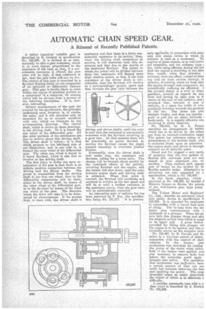
Several arrangements of the gear are • covered by the specification, the principle underlying each, however, is, of course, • the same, and it will therefore only be necessary for us • to concern ourselves with one, which we illustrate by the acconipanying drawings. The central shaft, which is shown on these drawings, is the driving shaft. To it is keyed the sun wheel of the differential gear. All the other portions of the mechanism are free to revolve about this driving shaft.
• a which projects to the. le-Iand aide of our illustration, and, in one with it, is formed the outer wheel of the differentiel gear. The other sun wheel is keyed to • a heavy flywheel, which is also free to revolve on the driving shaft. The first thing to strike one upon examination of the gear is that there is no • definite positive connection between the driving and the driven shafts. The power is transmitted, from the driving shaft to the first sun wheel, then to the differential components, and by them, either to the driven shaft, by means of the outer wheel of the differential gear, or to the flywheel by means of the other sun wheel of the gear. The direction • which the drive will take is to he determined by circumstances. If ire assume that, to start with, the driven shaft is stationary and that there is afairly considerable resistance to its motion, then, when the driving shaft commences to revolve, it will encounter both this resistance and that due to the inertia of the stationary flywheel. The extent to which the power will be divided between these two resistances will depend upon their relative extent, so that, if the load' resistance of the driven shaft is considerable, then the flywheel will revolve at a correspondingly greater speed and thus increase the peas ratio between the
driving and driven shafts, until the ratio is such that the resistance is conveniently overcome with the flywheel revolving at a good rate. At that moment there will be practically_ no peeves' devoted to moving the flywheel except the slight amount necessary to overcome journal friction.
Presumably, once the driven shaft is well under way, the resistance will decrease, calling for a lower ratio. The change will be brought about quickly by the combined efforts of the quickly revolving flywheel and the engine, and the former will slow down, until the ratio between engine shaft and driving shaft is °ea.-meted. When that point is reached, the flywheel will accelerate and continue to revolve at the new speed and will do so until a farther variation in the resistance occurs, when the gear ratio will be automatically corrected. An interesting type of radiator fan has been patented by F. -Kee, the specification being No. 131,317. It is particu
larly applicable in connection with stem cars and steam lorries in which th radiator is used as a condenser. Th engines of these chassis, as is well knows
reversible, and the ordinary type c fan, while being efficient during the tim that the engine is revolving in one dire( tion, would,. when that direction i reversed, have the effect, iitatead of drav jog cold air from outside through th radiator, of pushing warm air from abet the engine through that component, flit considerably reducing its efficiency. I the present design is a cowl or conie partition, circular as regards its oute form and' having its apex near to ti
• centre of the rear of the radiator, and arranged that, between it and tf radiator, is a space the width of whit graclnelly increases towards the perimeb
• of the fan. The latter has plai: straight blades, and does not operate • push or pull the air either forwards 4 backwards. It is equally effective win
revolving in either direction. No. .136,544, by M. L. Pourct describes an arrangement of turbin which has to be._ driven by the exhau ._gas from an internal-combustion engin The patent has reference rather to tl arrangement of . the turbine itself, whi( is mounted freely upon an extension the engine shaft, and drives it, through compact set of epicyclic gears. Snead and Co.. suggest a new meth( of ensuring that the two spiders of flexible disc universal joint are mai tamed in true alignment one wi another. They connect. each apposit pair of busses on the spiders by th flexible metallic strips. Alternative co stractions are also suggested by t: specification, whioh is No, 143,489.
In the shock • absorber, which patented in No. 146.932, by Societe ii Meteors Gnome et illione the princis of the well-known gear :type pump utilized.
The Vulean Motor and Engineeri Co., Ltd., describe an automatic lubri( tion safety device in specification i153429. It is intended for esriployme in eonnectiipn with a forced feed syste of oiling. The by-pass from the air( lation pipe communicates with t underside of a. plunger. When the pr. sure falls this plunger drops and earl the magneto witch wire which is coup.] to its upper end. A press button provided for lifting this plunger vii the engine is to be started, and this et venientiv -serves as the magneto (mit( No. 153,467, by TI, Garrett and Sol refers to a previous patent of theirs connection with•the control :of elect. vehicles. In the former, pate meohaniem was described for cutting the power of the motor when either both of the brakes were applied, and
• was necessary to remove both bra] before the controller could again brought into action. The operation that mechanism was ineffective, becai a certain amount of time was nee sarily bet between removing the bra] and applying the power. The presi invention' refers• to detail ocmstructit the object of which is to eliminate g difficulty.
A peculiar pneumatic tyre with a N I deep tread is described by J. Donkin 'No. 153,508.