Hydromechanical Infinitely variable Transmission
Page 66

Page 67

Page 68

If you've noticed an error in this article please click here to report it so we can fix it.
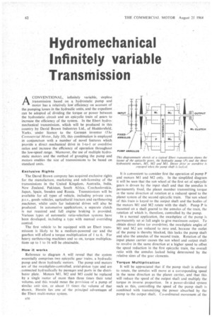
ACONVENTIONAL, infinitely variable, stepIess transmission based on a hydrostatic pump and motor has a relatively low efficiency on account of the pumping losses in the hydraulic units, and the expedient can be adopted of dividing the torque or power between the hydrostatic .circuit and an epicyclic train of gears to increase the efficiency of the system. In the Ebert hydromechanical transmission, which will be produced in this country by David Brown Industries Ltd., of Huddersfield, Yorks, under licence to the German inventor (The Comthercial Motor, July 10), this combination is employed in conjunction with a number of novel features which provide a direct mechanical drive in 1-to-I or overdrive ratios and increase the efficiency of operation throughout the low-speed range. Moreover, the use of multiple hydrostatic motors and the method of grouping the pump and motors enables the size of transmissions to be based on standard units.
Exclusive Rights
The David Brown company has acquired exclusive rights for the manufacture, marketing and sub-licensing of the transmissions in the United Kingdom. Australia, India, New Zealand, Pakistan, South Africa. Czechoslovakia. Japan, Spain. Sweden and Russia. Transmissions will be available for all types of vehicle, including private cars, p.s.v., goods vehicles, agricultural tractors and earthmoving machines, whilst units for industrial drives will also be produced. In automotive applications, a separate clutch is not -required and full engine braking is provided. Various types of automatic ratio-selection systems have been developed, in:Juding a type with manual overriding control.
The first vehicle to be equipped with an Ebert transmission is likely to be a medium-powered car and the gearbox will afford a torque multiplication of 1 to 6. For heavy earthmoving machines and so on, torque multiplicar tions up to I to 16 will be obtainable.
How it works
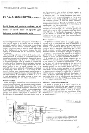
Reference to diagram A will reveal that the system essentially comprises two epicyclic gear trains, a hydraulic pump and three hydraulic motors. The pump and motors' are of the swashplate-controlled, axial-piston type and are s connected hydraulically by passages and ports in the distributor plate. Motors MI, M2 and M3 could be replaced by a single motor of more than three times their total volume, and this would mean the provision of a pump of similar unit size, or about 11 times the' volume of that shown. Herein lies one of the principal advantages of the Ebert multi-motor system. It is convenient to consider first the operation of pump P and motors MI and M2 only. In the simplified diagram it will be seen that the sun wheel of the first set of epicyclic gears is driven by the input shaft and that the annulus is permanently fixed, the planet member transmitting torque in the same direction of rotation at a reduced speed to the planet system of the second epicyclic train. The sun wheel of this train is keyed to the output shaft and the bodies of the motors MI and M2 rotate with the shaft. Pump P is mounted on a shaft geared to the annulus of the train, the rotation of which is, therefore, controlled by the pump.
In a normal application, the swashplate of the pump is permanently set at full angle to give maximum output. To obtain direct drive tor overdrive), the swashplate angles of MI and M2 are reduced to zero and, because the outlet of the pump is thereby blocked, this locks the pump shaft and also the annulus of the second train. Rotation of the input planet carrier causes the sun wheel and output shaft to revolve in the same direction at a higher speed to offset the speed reduction in the first epicyclic train, the overall ratio with the annulus locked being determined by the relative sizes of the gear elements.
Torque Multiplication
It will be appreciated that if the pump shaft is allowed to rotate, the annulus will move at a corresponding speed in the same direction as the planet carrier, and that this will reduce the speed of the output shaft and multiply the torque in inverse proportion. In a power-divided system such as this, controlling the speed of the pump shaft is combined with transmitting the power absorbed by the pump to the output shaft, Co-ordinated movement of the motor swashplates from the zero position permits fluid to flow from the pump to the motors, and the increase in pump-shaft speed is directly proportional to swashplate displacement and the effective combined capacity of the motors. Pump-shaft speed is twice the output shaft speed at full displacement of the motors because the total capacity of the motors MI and M2 is double the capacity of the pump.
In the limiting full-stroke position of the motor swashplates, two-thirds of the torque is transmitted through the hydraulic system and one-third through the epicyclic gears, torque multiplication being 1 to 3. A further increase in torque multiplication could be obtained by reducing the swashplate angle of the pump, thereby increasing the speed of the pump shaft relative to output-shaft speed, but this would demand a rise in system pressure and, as a preferable alternative, additional multiplication is obtained by employing a third motor, M3. It is worthy of note, however, that the pump swashplate angle may be varied in systems incorporating a third motor when applied to heavy machines requiring a multiplication in excess of I to 8. In such applications, the slight increase in noise and reduction in efficiency in a low ratio is acceptable.
Motor Rotates
When the stage is reached that torque multiplication in excess of 1 to 3 is required, the swashplate control engages a small hydraulic clutch, which causes motor M3to rotate at three times the prevailing output-shaft speed—that is, at its medium designed speed. Initially, the swashplate angle is zero and the motor cannot receive fluid. Therefore, the clutch is under no load at the instant of engagement. As the plate angle is automatically increased, pump speed is also increased, and when the limit of motor capacity is reached the pump shaft is operating at five times the speed of the output shaft. This gives a transmission speed reduction of 6 to I and a torque multiplication of 1 to 6, three times input torque being produced hydraulically and the remaining multiple of three by direct mechanical means. It is this use of gearing to contribute to torque multiplication that assists materially in the maintenance of high efficiency over the torque range.
For heavy-vehicle applications, motor M2 can be arranged to drive through 2-to-I reduction gearing and motor M3 through a 4-to-1 reduction, giving an overall ratio of 8 to I. As stated earlier, the capacity of the pump can be reduced to increase the speed ratio range still further, so that any ratio spread within normal practical
requirements can be obtained. , Servo-operated
In operation, automatic control of swashplate angles is provided by a servo-operated cam plate, the movement of which is subject to engine speed, road speed and throttle position. The profiles of the cam plate can be readily varied to cater for particular requirements and, as mentioned, a manual overriding control can be incorporated. Reverse is obtained by moving the swashplate of the pump " overcentre ", which causes the annulus of the epicyclic gear to rotate in the opposite direction, and overdrive is engaged by moving the motor swashplates overcentre.
it is pointed out by David Brown engineers that the efficiency ot a hydraulic motor increases with speed up to a limit imposed by mechanical considerations. The use of four units with inared drive enables the size and cost of the hydraulic system to be reduced, it is claimed, to between one-third and one-sixteenth the size and cost of a two-unit hydrostatic system, depending on the required ratio spread, in addition to providing improved efficiency. In direct drive an efficiency of 94 per cent is obtainable, whilst at a torque multiplication of 1 to 6, the efficiency is about 80 per cent. Operating pressures are purposely restricted to 3,000 lb./sq. in. and the system can be designed to operate at no more than 1,470 lb./sq.in. in the 1-to-1 to 1-to-2 torque-multiplication range.
Compact Installation Possible
As shown in diagram B, in a typical application the transmission can be fitted in the space normally occupied by a conventional mechanical gearbox, and the cost should initially be approximately equal to that of a torqueconverter and epicyclic-gear-train type transmission. When the transmission is produced in quantity the cost may well be considerably less. The diagram indicates a possible arrangement for _a light-vehicle transmission with 1-to-6 torque multiplication which provides clutch disconnection of all motors in the 1-to-1 ratio and half-pressure operation down to 1-to-2 torque multiplication, both of which are patented features.
Apart from the greater driver convenience that the transmission will afford, it should proyide improved performance and fuel consumption by virtue of automatic selection (without lag or release of the throttle pedal) of the optimum ratio for any instantaneous set of operating conditions. In top gear, the loss of efficiency compared with a mechanical gearbox is about 2 per cent, which is a function of the power absorbed by the epicyclic gears, but this loss could be more than offset in practice in the case of a design incorporating overdrive by automatic transition into any. degree of overdrive that road conditions permit and at the moment that these conditions obtain. Selection of "normal drive ", "neutral ", "reverse ", "parking lock ", "push start" and several stages of "low drive" can be performed with a steering-column lever or a short, floor-mounted control stick. Manual selection of neutral moves the pump swashplate to the zero-angle position, whilst drive disconnection when the vehicle is brought to rest in traffic is obtained by automatic opening of a by-pass valve. The lowest ratio can be selected at any road speed to give maximum overrun braking, as one of the control circuit governors ensures that the transmission does not overspeed the engine. At this stage, higher-than-normal overrun braking is then obtained through the regenerative property of the hydraulic system.
Reduced Stresses
With further reference to grouping the hydraulic units on the distribution plate, this affords reduced internal stresses by virtue of the balance achieved both mechanically and hydraulically. Of first importance with regard to production costs, a basic type of quadruple-unit hydrostatic block with a rating of 50 b.h.p. could conveniently be used in multiples for transmissions with ratings of 100 b.h.p., 150 b.h.p., 200 b.h.p., and so on, Whilst an 80-b.h.p. block could be employed for outputs of 160 b.h.p., 240 b.h.p. and 320 b.h.p. In each case, the multi-block unit would be considerably smaller and lighter than the equivalent pump-and-motor pair.


