


Protected Ball Joint
Page 66
If you've noticed an error in this article please click here to report it so we can fix it.
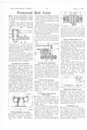
BALL joints are the subject of patent No. 811,340 which discloses a design of joint having a spherical dirt-excluder. (T. Hirst, 163 Woodside Avenue, Coventry.)
The ball stud is of the usual form and is fixed by a taper and nut. Its housing comprises a shell (1) which forms the ower bearing (2). It also encloses (by a turn-over at the point 3) a top hemispherical bearing (4). The turned-over portion is said to exert a gripping force between the halves, which persists even when wear has occurred.
The lower part is extended to form a thin edge (5) which bears on a spherical cup (6). This is the dirt-excluding seal and it is kept under scaling force by a compressed rubber ring (7). The bearing faces may he formed in nylon; an insert (8) shows how it may be applied.
DIAPHRAGM AIR SPRING
DATENT No. 811,546 describes an airsuspension layout utilizing diaphragm-type springs. (General Motors Corp., Detroit, Michigan, U.S.A.)
Referring to the drawing, the road wheel is mounted on an arm (1) pivoted to the frame at one end. The arm carries the piston (2) of the air spring, the cylinder being shown in part at 3.
The flexible rolling lobe (4) is attached to both the cylinder and the piston and as the piston rises, the air in the cylinder is compressed. When the piston has risen sufficiently to bring the tyre into contact with the taper portion (5) its effective area is increased and the suspension becomes harder. The patent states that by designing the piston to a suitable outline, any desired spring characteristic may be obtained.
POWER-STEERING CONTROL
A CONTROL for power steering des rI in patent No. 811,980 is claimed to be sensitive and to give a very rapid response. (Daimler-Benz u32
A.G., Stuttgart-Unterttirkheim, Germany.) This is. achieved by using the friction between the worm and the nut of the normal steering box though this is kept at a low value due to the use of a hailbearing thread.
Referring to the drawing, the worm (1) turns in its nut (2) on bails, the outgoing balls being returned via a re-entrant tube (3). The nut is restrained from rotation by a stub (4) which projects through a gap in the casing and engages with an annular groove in a piston-valve (5) controlling the hydraulic fluid.
The axial movement of the nut is transmitted through a short link (6) to an arm on the end of the drop-arm shaft (7). The power piston (not shown) is located close to the nut and slides axially with it.
CONTROLLED MISFIRING
PATENT No. 812,862 describes a scheme for controlling the power output of an engine by non-firing strokes created by cutting off the fuel to one or more cylinders. The scheme is intended for engines employing petrol injection. All cylinders are affected in turn so as to even out local overload and prevent fouling of the plugs. The patent comes from General Motors Corp., Detroit, Michigan, U.S.A.
PNEUMATIC BRAKES
PATENT No. 813,001 comes from Fabbrica Italiana Magneti Marelli S.p.A., Milan, Italy, and deals with a distributor valve for pneumatic braking systems. It can be set so as to give operation in sequence of two sets of brakes, as required in tractor-trailer combinations.
AUTOMATIC DISC BRAKE ADJUSTMENT
PATENT No. 812,003 describes an automatic adjustment device for disc brakes as used on road vehicles, but it also covers the same principle applied to drum brakes and clutches. (Dunlop Rubber Co., Ltd., 1 Albany Street, London, N.W.1.)
The drawing shows a brake in which 1 is the disc, 2 the friction pads and 3 the caliper connecting both sides of the mechanism. The pads can be thrust inwards on to the discs by pistons (4) which are either hydraulically or pneumatically operated. Retraction is provided by a resilient annulus (5).
Automatic adjustment is Performed by pins (6) which are held by their heads (7) in shallow recesses. One-way friction grips (8) allow the pistons to move towards the discs without moving the pins, but prevents their return, so correcting for wear of the pads. The necessary small working clearance is permitted by a Belleville washer on the head of each pin.
FRONT-WHEEL-DRIVE VAN A DESIGN for a light van with a low rtloading height provided by the use of front-wheel drive, is shown in patent No. 811,716. (Regie Nationale des Usines Renault, 8-10 Avenue Emile Zola, Billancourt, Seine, France.)
The drawing shows a plan view of the proposed layout. The engine (I), with its gearbox, is located at an angle to allow the gearbox output shaft to carry the pinion of the axle gearing (2). Independent suspension is used, and universal joitits are incorporated in each half-axle, the axle casing being attached to the chassis.
The one-sided load caused by the engine can be offset by carrying the accumulators (3) and the spare wheel (4) on the opposite side. The angular position of the engine permits the insertion of a starting handle if necessary from the side. The patent envisages the possibility of using hydraulic transmission and a magnetic• clutch with the scheme.
IMPROVED PISTON RING
PATENT No. 811,210, from Sealed Power Corp., 2001 Sanford Street, Muskegon, Mich., U.S.A., shows a design for a composite piston ring. It consists of thin upper and lower rings which make contact with the groove, separated by a spring ring expanding in both horizontal and vertical directions. The specification shows the stages in the manufacture of the ring.
REVERSING AID
PATENT No. 811,784 describes a warning device for use when backing a vehicle. It consists of a telescopic unit projecting from the rear which, when forcibly shortened by contact with an obstruction, warns the driver by a light or by a buzzer. The patent comes from E. Sandal!. Engineers' Dept., 36 Pembroke Place, I.iverpool 3.