


Improvements in Sparking Plugs
Page 62
If you've noticed an error in this article please click here to report it so we can fix it.
ACCORDING to patent No. 693,836, the normal type of sparking plug, with its flanged ceramic insulator, often fails due to cracks and other defects arising from the stresses imparted during assembly. The riatent describes a design of plug which is free from this defect. The inventor is A. Thies, 1 HUttenstrasse, Nienburg, Weser, Germany.
• The inSnlator in this case is a sleeve (1) made of sintered corundum, and it is surrounded by a bush (2) made of electrolytic copper. In assembly, the bush and insulator are placed in position and heavy endwise force is then applied. This squeezes the copper into the keying groove (3) making a joint claimed to meet both insulating and gas-sealing requirements.
An outer sleeve (4) of insulating material is then inserted and secured by a gland-nut which also grips the high-tension lead by means of a deformable packing (5). A feature of the scheme is that the copper ring effectively screens any high-frequency waves, matter of importance in these days of television, as no separate suppressors would be necessary.
METHOD` OF PRODUCING A HIGH-SURFACE FINISH QUPER-FINISHING is a subject
■ -.-7 receiving much attention lately, and a simplified method of obtaining it forms the subject of patent No. 694,184 (Girling, Ltd., King's Road, Tyseley, Birmingham). The need for such finishes arises particularly in the manufacture of sliding plungers, such as are used in telescopic shock-absorbers and similar mechanisms.
The rod is first ground to a moderately good finish, say 20 micro-in., and is then subjected to a rolling operation. The drawing illustrates the principle involved; it shows the workpiece (1), a cylindrical roller (2) and a hyperbolically curved roller (3) set at a slight angle.
As the shaft is rotated, pressure is applied by the rollers, causing it to progress endways as it runs. The advantage of the scheme is that the .finish put on the work is far higher than that of the rolls which create it; for example, rolls finished to 7 micro-in. will produce work smooth to within half a micro-in. The patent also shows the actual construction of the rolling machine.
A SIMPLE PILOT-INJECTION NOZZLE
THE advantages of pilot injection for 1 oil engines are generally admitted, but the means used to obtain it are Often complex. A particidarly simple scheme is shownin patent No. 693;312, by Robert Bosch G.m.b.H., Stuttgart-W, Germany.
The patent -describes an injector needle-varve which has a self-interruptmg action during the discharge stroke. The drawing shows, on an enlarged
scale, the tip of an injection . nozzle according to the invention, The valve is pressure-operated, being forced downwards by the charge of fuel. The first movement unseats the coned portion (1) and permits a restricted amount of fuel to pass. Further downward movement then cuts off the fuel as soon as the parallel portion (2) enters the close-fitting bore (3) in the nose.
Continued movement eventually causes the whole coned part to emerge from the bottom, as indicated in broken line. The remaining part of the charge then has an unobstructed path into the cylinder.
MOUNTING RUBBER BUSHES
RUBBER bushes used in swinginglink suspension link suspension systems may not allow sufficient deflection under extreme conditions, and patent N,; 693,531, shows a scheme' for making allowances for this. The rubber bush is held in-a sleeve which is, itself, a frictional fit in the housing.
Whilst the rubber will absarb. all normal deflection, abnormal movement Can shift the frictional sleeve round to a new position. The patentee is DaimlerBenz A.G:, Stuttgart-Untertiirkbeirn, Germany.
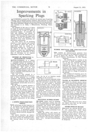
RUBBER MOUNTING FOR INJECTION-PUMP GOVERNORS
TO insulate an injection-pump governor from vibration is the aim of an improved construction shown in patent No. 694,152. The patentees are H. and F. Deckel, Garatshausen 22, Post Tutzing, Germany.
The drawing shows a section of the governor in which centrifugal weights (1), as they fly outwards, move the control-rack pins (2) via bell-cranks indicated by broken lines (3). The governor hub, instead of being directly attached to the spindle, is carried by a rubber ring (4) which is bonded both to the hub and to a flange (5) carried by the spindle.
This method of mounting gives the whole mechanism a limited freedom which prevents the destructive action of transmitted vibration.
WATER AS FILTERING MEDIUM
PATENT No. 693,541, shows a device which removes foreign bodies from fuel. by washing them out with water. The patentee is Ditta Fratelli Lombardi and Dotti, Rue Dante 7r, Brescia, Italy.
Referring to the drawing, the body of the unit is filled with water up to the level indicated at I. Fuel enters via port 2 and passes through the central tube to flow upwards through the water, finally leaving by the connection 3.. Baffles (4) compel the fuel to follow an extended path and so pass through more water.
Heavy solids sink in the water, whilst the lighter ones float on the border between fuel and water.
DOORS OPERATE BRAKES
PATENT No. 694,228 (Bendix Aviation Corporation, South Bend, Indiana, U.S.A.) shows a scheme for linking the doors and the brakes of a passenger service vehicle. If the doors be opened during running, the brakes will automatically be applied. Full 'braking force is not used, as it would be dangerous.