


A Guy Electric Automatic Clutch
Page 62
If you've noticed an error in this article please click here to report it so we can fix it.
I N the transmission system dealt with in patent No. 450,034 by Guy Motors, Ltd., Wolverhampton, C. K. Edwards and J. E. Reece, the difficulties encountered in the design of springs for the operation of a centrifugal clutch has led to the abandonment of this unit, and the adoption in its place of an electrically operated clutch. The accompanying drawing shows the assembly, which consists of a fluid coupling of the Fottinger type in conjunction with a superseding mechanical clutch for giving a straight-through drive; The clutch, for this purpose, is magnetically operated, an annular winding (1) being embedded in the driven member, with a slip-ring and current pick-up (2) on a smaller diameter.
The operation of the clutch, is controlled by the engine rpeed, for which .purpose a small centrifugal switch is fitted to some convenient point on the engine. Furthermore, the gear lever is provided with an interrupter switch, so that whenever a ratio change is to be made the clutch is automatically freed.
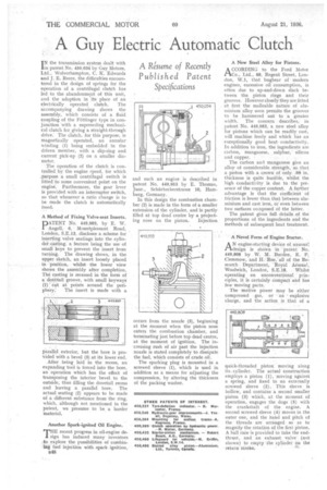
A Method of Fixing Valve-seat Inserts.
PATENT No. 449,989, by E. W. Angell, 6, Mountpleasant Road, London, S.E.13, discloses a scheme for inserting valve seatings into the cylinder casting, a feature being the use of small keys to prevent the insert from turning. The drawing shows, in the upper sketch, an insert loosely placed in position, whilst the lower view shows the assembly after completion. The casting is recessed in the form of a dovetail groove, with small keyways (1) cut at points around the peri
phery: The insert is made with a parallel exterior, but the bore is provided with a bevel (3) at its lower end. . After . being laid in the recess, an expanding tool is forced into the bore, an operation which has the effect of transposing the interior bevel to the outside, thus filling the dovetail recess and leaving a parallel bore. The actual seating (2) appears to be made of a different substance from the ring, which, although not mentioned in the patent, we presume to be a harder material.
Another Spark-ignited Oil Engine.
THE recent progress in oil-engine design has induced many inventors to explore the possibilities of combining fuel injection with spark ignition,
848 and such an engine is described in patent No. 449,953 by E, Thomas, Junr., Schtirbeckerstrasse 10, Hamburg, Germany.
In this design the combustion chamber (2) is made in the form of a smaller extension of the cylinder, and is partly filled at top dead centre by a project ing nose on the piston. Injection occurs from the nozzle (3), beginning at the moment when the piston nose enters the combustion chamber, and terminating just before top dead centre, at the moment of ignition. The increasing rush of air past the injection nozzle is stated completely to dissipate the fuel, which consists of crude oil.
The sparking plug is mounted in a screwed sleeve (1), which is used in addition as a means for adjusting the compression, by altering the thickness of the packing washer. A New Steel Alloy for Pistons.
ACCORDING to the Ford Moto' Co., Ltd., 88, Regent Street, London, W.1, that bugbear of modern engines, excessive oil consumption, is often due to up-and-down slack between the .piston rings and their grooves. However closely they are fitted at first the malleable nature of aluminium alloy soon permits the grooves to be hammered out to a greater width. The concern describes, in patent No. 449,983, a new steel alloy for pistons which can be readily cast, will machine freely and which has an exceptionally good heat conductivity. In addition to iron, the ingredients are carbon, manganese, sulphur, silicon and copper.
The carbon and manganese give an alloy of considerable strength, so that a piston with a crown. of only .09 in. thickness is quite feasible, whilst the high conductivity is due to the presence of the copper content. A further advantage is that the coefficient of friction is lower than that between alu:minium and cast iron, or even between two surfaces composed of the latter.
The patent gives full details of the proportions of the ingredients and the methods of subsequent heat treatment.
A Novel Form of Engine Starter.
AN engine-starting device of unusual design is shown in patent No. 449,808 by W. M. Burden, E. P. Clemmow, and H. Roe,' all of the Research Department, Royal Arsenal,
Woolwich, London, S.E.18. Whilst operating on unconventional principles, it is certainly compact and has few moving parts.
The motive power may be either compressed gas, or an explosive charge, and the action is that of a quick-threaded piston moving along its, cylinder. The actual construction employs a piston (1), moving against a spring, and fixed to an externally screwed sleeve (2). This sleeve is hollow, and contains a second smaller piston (3) which, at the moment of operation, engages the dogs (5) with the crankshaft of the engine. A second screwed sleeve (4) moves in the outer one, and the hand and pitch of the threads are arranged so as to magnify the rotation of the first piston. A ball raCe is provided to take the endthrust, and an exhaust valve (not shown) to empty the cylinder on the return stroke.