


THE BRAKING SIX-WHEELERS.
Page 16
Page 17
Page 18
Page 19
If you've noticed an error in this article please click here to report it so we can fix it.
IT is nowadays generally accepted that four-wheel brakes are the proper and most effective means for .checking the speed of private cars and their larger brethren, the passenger coaches or buses. But what of the six-wheeler? For this type brings in an entirely new set of conditions of service and so the problem becomes a different proposition .altogether. Should all wheels be braked, either equally or otherwise, or is it sufficient to fit two pairs of wheels with brakes? If so, bow should they (the four brakes) be disposed among six wheels?
Here we have one set of questions (for there are others !) which could evoke an argument second only in severity to the little affair carried on between the years 1914 and 1918 if the extremists among the adherents to each type ever become embroiled in it. The writer realizes that various schools of thought exist, and that each has good arguments to show that his particular solution is correct. The position, therefore, is rather difficult, and it would seem that a preliminary canter through "first • principles" would help matters not a little and tend somewhat to clear the air.
The very essence of effective braking on any class of vehicle is to attain the _ maximum permissible retardation in unit time compatible with the comfort of any occupant of the vehicle and the. safety of the structure Itself (the loading must be such that various. components are broken up). Further, it must be possible to retard the progress of the vehicle in a gradual manner, if desired, which means to say that whatever the maximum retardation rate happens to be, it must be possible to use the mechanism supplying that retardation in a progressive manner so that, by the control of the driver, the reduction in speed can either be gradual or fierce, as the exigencies of the circumstances demand.
Now, in a motor vehicle, there is only one reasonable medium through which a braking effect may be applied, i.e., through the contacting surfaces of the wheels with the ground. That means to say that whatever effort be exerted, such effort must be transmitted through the frictional grip between the tyres and the road. This brings us to a point which is really of great importance when considering the subject under review, for, With. the modern, highly efficient tyre tread, it is possible to obtain a virtual coefficient of friction greater than unity. Indeed, experiments that have been conducted have given a coefficient of 1.2.
c32 • •
, Now, it is obvious that what may be plainly termed "tyre grip" is definitely proportional to the area of the tyre in contact with the road and the weight pressing the two elements into contact. In other words, weight distribution is an item of great importance. Let us turn to another aspect of the case. Although not at first very apparent, the position of the centre of gravity of any vehicle is a matter which must be considered when plotting the layout for the braking system. A little reflection will soon show the reason for this. Imagine a vehicle—diagrammatically shown in Fig. 8—moving along a road at any given speed, say,
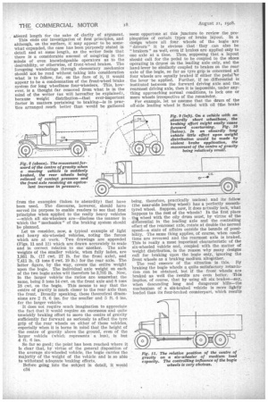
for example, 25 m.p.h. Then let the brakes be suddenly applied. What happens to the passengers? Anybody knows that they all get pitched forward more or less violently owing to a property known to engineers as "inertia." As with the passengers, so with the vehicle; the virtual centre of gravity in the position marked, moves forward in company with the occupants of the seats, the amount it moves forward being proportional to the rate of deceleration.
We will now consider what is happening to the weight distribution. Let us imagine a constant deceleration. The csg, moves forward and stays forward until the vehicle stops, when the energy absorbed by the springs, etc. (due to the movement of the e.g.), releases itself and the vehicle pitches back into its normal position again (Fig. 8). The sensations arising from these movements of the centre of gravity are, of
course, everyday experiences of most of us who ride in any sort of motor vehicle. In the process just outlined the movement of the e.g. causes a re-shuffling cig the distribution of the load, the rear wheels losing some of the weight and the front wheels gainingthe equivalent amount. In the case of a high vehicle with an absurdly short wheelbase (as in Fig. 9), it is clear that a very rapid deceleration may so affect the weight distribution as to place the whole of the weight upon the front wheels and none on the rear wheels. Indeed the rear axle •weight • may even be reduced to a negative quantity, which would, of course, make the vehicle pitch forward and dig its nose into the ground. This is, of course, assuming that all wheels of the vehicle are being braked.
With rear brakes only, it is impossible to cause overturning, because the forward movement of the e.g. is controlled (and so kept within safe limits) by the fact that, so soon as the rear axle tends to lift, the braking effect is diminished (by loss of the frictional contavt of the tyres with the ground), the e.g. automatically.movink back again.
The ease of the long wheelbase vehicle is entirely different. We will imagine an extreme case such as is diagrammatically shown in Fig. 10. Here, the majority of the weight is concentrated over the rear axle and, by virtue of the shape of the vehicle, the e.g. is placed
low. Violent braking (which means violent deceleration) with a vehicle of this type offers a set of conditions entirely different from those attaching to the short wheelbase vehicle already diseuSsed. The actual movement of the e.g. in the long wheelbase vehicle can, for the sake of argument, be taken as being approximately equal to the movement in the short wheelbase model, but the effect on the weight distribution is, of course, vastly dissimilar. In other words, with an ultra short wheelbase vehicle and a relatively high centre of gravity, the front wheels assume a controlling interest in the braking system. On a vehicle with a long wheelbase and having a comparatively low centre of gravity, however, the controlling effect more often than not remains with the rear wheels. although, of course, when normal proportions are assumed for the layout of the vehicle, the shifting of the e.g. is more marked than that demonstrated in Fig. 10, where the wheelbase has been carried to an
absurd length for the sake of clarity of argument.
This ends our investigationof first principles, and although, on the surface, it may appear • to be somewhat expanded, the case has been purposely stated in detail and at some length, as the writer feels that there is a considerable amount of misgiving in the minds of even knowledgeable operators as to the desirability, or otherwise, of front-wheel brakes. The foregoing wanderings through elementary mechanics
• should not he read without taking into consideration what is to follow, for, on the face of it, it would appear to be a condemnation of the front-wheel brake system for long wheelbase four-wheelers. This, however, is a thought far removed from what is in the mind of the writer (as will hereafter be explained), because weight distribution—that ever-important factor in matters pertaining to braking—is in practice arranged much better than would be gathered from the examples (taken to absurdity) that have been used. The discourse, however, should have served its purpose to enable readers to see that first principles when applied to the really heavy vehicles —which all six-wheelers are—disclose the manner in Which the "mechanics " of the braking system should be planned.
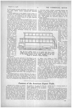
Let us consider, now, a typical example of light and heavy six-wheeled vehicles, noting the forces which are at work. Two drawings are appended (Figs. 11 and 12) which are drawn accurately to scale and in correct relation to one another. The axle weights of the smaller vehicle, when fully laden, are 1,931 lb. (17 cwt. 27 lb. for the front axle), and 7,411 lb. (3 tons 6 ewt. 19 lb.) for the rear axle. The latter figure, by the way, covers the entire weight upon the bogie. The individual axle weight on each of the two bogie axles will therefore be 3,705 lb. Now, In the larger vehicle the ratios are somewhat the same, being 3 tons 14 cwt. on the front axle and 8 tons 18 cwt. on the bogie. This means to say that the centre of gravity is much closer to the rear axle than the front. Broadly speaking, these theoretical dimensions are 2 ft. 6 ins, for the smaller and 5 ft. 0 ins. for the larger vehicle.
It does not reqttire much imagination to appreciate the fact that it would require an enormous and quite unwieldy braking effort to move the centre of gravity sufficiently far forward as seriously to affect the tyre grip of the rear wheels on either of these vehicles, especially when it is borne in mind that the height of the centre of gravity above the ground, even of the larger vehicle (which represents a bus), is but 4 ft. 6 ins.
So far so good; the point has been reached where it Is clear that, by virtue of the general disposition of the average six-wheeled vehicle, the bogie carries the majority of the weight of the vehicle and is so able to withstand adequate braking efforts. Before going into the subject in detail, it would c34
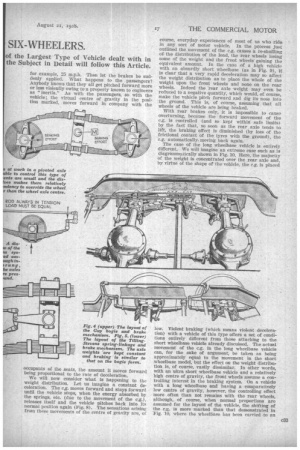
seem opportune at this juncture to review the propinquities of certain types of brake layout. In a design where all four wheels of the bogie are " drivers " it is obvious that they can also be " brakers" as well, even if brakes are applied only to one axle at a time. Thus, supposing that a layout should call for the pedal to be coupled to the shoes operating in drums on the leading axle only, and the hand-lever be similarly coupled to brakes on the rear axle of the bogie, so far as tyre grip is concerned all four wheels are equally braked if either the pedarbr the lever be applied. Further, if no differential is instituted between the forward driving axle and the rearmost driving axle, then it is impossible, under anything approaching normal conditions, to lock one or more wheels irrespective of the remainder.
For example, let us assume that the drum of the off-side leading wheel is flooded with oil (the brake
being, therefore, practically useless) and its fellow (the near-side leading wheel) has a perfectly smoothtyred wheel. Suppose, now, it does actually lock, what happens to the rest of the wheels? In the first place thet wheel with the oily drum must, by virtue of the differential in the leading axle and the controlling effect of the rearmost axle, rotate at double the normal speed—a state of affairs outside the bounds of possibility. The same thing applies, of course, when cotaditons are reversed and the rearmost axle is braked. This is really a most important characteristic of the six-wheeled vehicle and, coupled with the matter of weight distribution, is the reason why many designs -call for braking upon the bogie only,. ignoring the front wheels as a braking medium, altogether.
, The real essence of the situation is this. By braking the bogie wheels a quite satisfactory retardation can be obtained, but if the front wheels are braked as well the results are even better. This implies, of course, that by using all six brakes—say, when descending long and dangerous hills—the mechanism of a six-braked vehicle is more lightly loaded than its four-braked counterpart, which results
in less heating of shoes and drums, less general wear and more lightly loaded controls—all desirable features.
Violent application of six brakes is apt to make retardation of a passenger vehicle too rapid for comfort and so in a bus operating in fiat country the fourwheel system is usually found to be quite sufficient for all practical purposes.
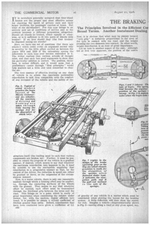
It might prove interesting to examine a few systems and see what forces are at work when braking occurs. Take, for example, the design shown in Figs. 1 and 2. This is a very popular type of axle mounting and one largely used for bus chassis. All the torque reactions are, of course, taken actually by the springs themselves, but the disposition of the two sets of springs is such that a great deal of curvature in the leaves is avoided—a great advantage, because the reaction when the vehicle comes to rest (and the springs unwind themselves, as it were) is reduced accordingly, to the satisfaction of the occupants of the seats. The overturn;ng couple, as shown in the diagram, is also comparatively small, so that, everything
considered, t ii e systemwould appear to be almost ideal for normal road requirements.
So far as the actual operation of the shoes is concerned, there seems to be no insuperable difficulty in reaching the halcyon state of equal application. The drawing of the Guy system shows how, by mounting the levers to all the brake rods on separate pivots, the movement of the wheels can be closely followed and equal shoe pressures maintained no matter what may be the position of the wheels relative to the vehicle. There is one very interesting point concerning this particular layout—the brake rods are inclined somewhat to the centres of the bogie and wheel axles. This is done to allow for the elongation in the spring as it becomes flattened under load. The principle is shown in Fig. 7.
The Morris system is entirely different; the bogie is so arranged with bogie reaction arms that all movements take the form of a parallelogram. To this end the spring connections are effected through spherical ioints, an arrangement that permits the axle to make a criss-cross motion without torsionally loading the springs to any measurable extent. The torque reaction is—as will be seen from the drawing in Fig. 3 —countered by means of suitable arms pivoted on a tube Vanning across the frame and above the bogie axle. The springs are therefore relieved of the braking stresses.
With independently sprung axles, the reactions are almost exactly as are found on the four-wheeled vehicle, and so the type hardly conies within the scope of an article such as this. There is, however, one interesting side-issue to this form of construction—the interconnected, independently sprung bogie (a long term, but expressive of the principle). We refer, of course, to the Tilling-Stevens type of suspension, where on each side of each axle there is a semielliptic spring, the rear ends of each spring (in pairs) being coupled, by links, bell-crank levers and con necting rods, in order to obtain interaction b e tween the two axles.
The "levelling up" of shocks, and so on, which the linking achieves, al s o means that the contacting pressure between the tyres and the road is more or less equalized. Thus, when the brakes are applied, a state
of affairs very similar to that obtaining in the bogie type of axle is, in effect, achieved. The braking reactions are of quite an elementary type, being approximately the same in both axles, no matter whether one pair of wheels only is braked or whether all four wheels are retarded.
With a subject such as this one could go on for ever almost, discussing the pros and cons of various forms of construction and the layout of different braking gears employed on modern chassis, partly because there is so much of interest, and partly due to the fact that individual designs, although similar in general layout, differ greatly in detail. There is, however, one side of the question that has not as yet been touched upon—the actual operating mechanism. An article dealing with the matter is in course of preparation and will appear in an early issue of The Co MM ereial Motor.