


EQUIPPING A COACH FOR WIRELESS RECEPTION.
Page 12
If you've noticed an error in this article please click here to report it so we can fix it.
High-frequency and Low-frequency Amplification Have Been Discussed Separately. This Instalment Deals With Them in Combination.
WE HAVE now taken the reader through the mysteries of both high-frequency and lowfrequency amplification. We have shown how, low-frequency amplification is most useful where increased volume of sound is required in the telephones, and high-frequency amplification where either increased range is sought., or where the aerial is poor. We can, of cowrie, combine both methods in one receiver, where the desiderata are both increased• range and great loudness of signal.
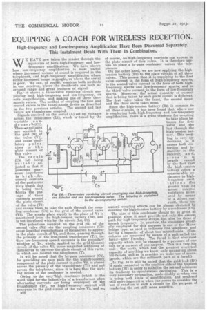
Fig. 16 shows a three-valve receiving circuit employing both high-frequency and low-frequency, or note magnification, and making use of three thermionic valves. The method of coupling the first and second valves is the tuned-anode device as described in the two previous articles. The second and last valves are transformer coupled. Signals received on the aerial (A) set up voltages across the inductance (Li), which is tuned by the variable c o ii.dense rk(01). These meotvoitages C2
are applied to le
the grid (G) of the valve (71), and cause oscillatory p u 1 s ations in the plate circuit of this valve The circuit (02, L2) bein suitably adjusted so that it possesses maximum impedence quency currents 82 of the particular --II. wave length that C5' is being used, blocks the passage of these currents around , the plate circuit of the valve (V1.) and causes them to take the path through the coupling condenser (03) to the grid of the second valve (V2). The steady plate supply to the plate of Vi is maintained from the high-tension battery (B2), and is not interfered with by the circuit (L2, 02). The pulsations received on the grid (G) of the second valve (V2) via, the coupling condenser (03) cause lopsided reproductions of themselves to appear in the plate circuit of V2, and these, passing through the primary of the iron-cored transformer (Tr), induce low-frequency speech currents in the secondary winding of. Tr., which, applied to the grid-filament circuit of the valve V3, cause magnified additions of themselves to traverse the plate circuit of this valve, in which are located the telephones (T).
It will be noted that the by-pass condenser (CO, for 'providing an easy path for the high-frequencz, component of the plate current in valve V2, is placeacross the primary of the transformer (Ti-) and not . across the telephones, since it is here that the sorting action of the condenser is needed.
Owing to the veryahigt. reactance (which is the word used for the inductivity of a transformer when alternating currents are being employed) of the transformer (Tr), no high-frequency current will reappear in the grid circuit of the valve V3, and so,
E
of course, no high-frequency currents can appear in the plate circuit of this valve. It is therefore useless to place a by-pass condenser across the telephones. On the other hand, we are now applying the hightension battery (B2) to the plate circuits of all three valves. This rneans that it is supplying to the first valve current in the form of high-frequency spurts, to the second valve current in the form of both highfrequency, spurts and low-frequency spurts, and to the third valve current in the form of low-frequency spurts. Moreover, the actual quantity of current that is being taken by each plate circuit is different. The first valve takes the least, the second more, and the third valve takes most.
Since the high-tension battery (B2) is common to all three circuits, it has been found that, where one is employing both high-frequency and low-frequency amplification, there is a great tendency for coupling to take place between the first valve and the last through the high-tension battery. This coupling is very undesirable, as it causes both distortion and instability in the
receiver, d, since it is largely caused by the fact that the high-tension battery offers a considerable resistance to highfrequency oscillations (far greater than its actual , internal resistance meas:ured by means of a direct -current), these unwanted coupling effects can be almost obviated by shunting the high-tension battery by a condenser (05).
The size of this condenser should be as great as possible, since it must provide not only the easiest path for high-frequency strays, but also for those of speech frequency. In practice, the condenser generally employed for this purpose is one of the Mansbridge type, as used in ordinary line telephony, and haring a capacity of about two micro-farads. (CondeLsers are measured by means of a unit called the farad—after Faraday. The farad is that electrical capacity which will be charged to a pressure of one volt by a current of one ampere. This is a very big unit ; the earth, which has the greatest electrical capacity of anything we know, only measuring about 100 farads, and so in practice we make use of microLterads, which are the millionth part of a farad.) .,1n Fig. 16 it will be noted that the grid leak (R1) 'is again connected to the positive side of the filament battery (B1) in order to stabilize the set and minimize it tendency to: spontaneous oscillation. This is a very necessary precaution, made doubly so when one is using both kinds of amplifiCation, and rendered still more imperative when one comes to consider the use of reaction in such a circuit for the purpose of rendering the set still more sensitive.